Note
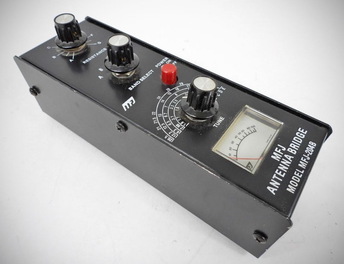
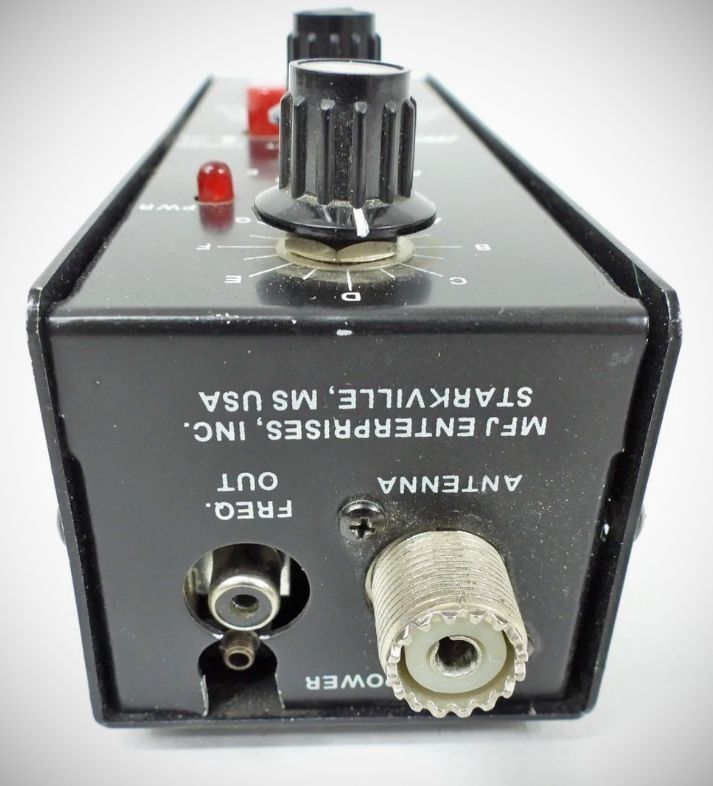
The MFJ-204(B) is a specialized Wheatstone bridge circuit designed to measure the resistive component of antenna impedance at a specific frequency. Unlike a standard SWR meter that requires a transmitter to be active, the 204 has its own internal low-power oscillator, allowing you to tune an antenna "cold."
The unit gives you a direct readout of your antenna’s SWR without the need for formulas or indirect readings. The MFJ-204B can also be used to adjust a tuner to match your antenna without the need for transmitting. The frequency coverage for the MFJ- 204B is from below 1.75 MHZ to above 30 MHZ in 5 user selectable bands.
It can be used to find the resonant frequency of your antenna, to find the SWR of your antenna at a particular frequency, and to find the frequency at which your antenna has the lowest SWR. You can also use the Antenna Bridge to adjust your antenna to a low SWR and to adjust an antenna tuner to match the transmitter to your transmission line. You can even find out if your antenna is resonant on more that one frequency.
The added benefit of using an Antenna Bridge over a SWR meter is that you can adjust antennas to impedances other than 50 Ohms. This is handy if you are using CATV hardline, Ladder line or any other non 50 ohm coax.
The MFJ-204B: In the early 1980s, MFJ updated the design to the MFJ-204B. This version is far more common because it remained in production for decades. The "B" model refined the oscillator stability and was often used in conjunction with a frequency counter for more precise readings.
The 204 series eventually gave way to the microprocessor-controlled SWR analyzers like the MFJ-259 in the early 1990s, which combined the bridge, oscillator, and frequency counter into a single digital display unit.
Features
– Portable: The MFJ-204B’s light weight, small size and internal battery capability makes it ideal for Field Day, travel or any time you need to check out a new antenna installation quickly easily.
– Stable: With built in AGC the MFJ-204B is accurate across the bands. No false readings.
Wide Range – Determine the RF Resistance of your antenna from 10 to over 600 ohms.
The 204(B) measures and identifies the following:
1. Feedpoint Resistance (R)
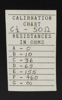
The unit features a calibrated dial (typically 0–500 ohms). By adjusting this dial while watching the meter for a "null" (the lowest possible reading), you can determine the actual resistive load of the antenna system. For most amateur radio applications, the goal is to see a null when the dial is set to 50 ohms.
2. Resonant Frequency
Because the device includes a built-in variable frequency oscillator, you can sweep through a band to find exactly where the antenna is resonant. At resonance, the inductive and capacitive reactance (X) cancel each other out (X=0). When the meter "nulls" out completely (drops to zero), you have found the point of resonance where the load is purely resistive.
3. Electrical Length and Velocity Factor
By using the bridge in conjunction with a known non-inductive resistor or a piece of coaxial cable, it can be used to:
Find the velocity factor of a mystery piece of coax.
Determine the electrical quarter-wavelength or half-wavelength of a feedline.
Tune matching stubs and traps without putting a signal "on the air" that could cause interference.
Technical Limitations
It is important to note that the MFJ-204(B) is a scalar instrument, not a vector analyzer. While it is excellent at finding the "dip" that indicates resonance, it does not explicitly tell you if an off-resonance reading is inductive (+j) or capacitive (-j). You have to determine that by slightly adjusting the frequency and watching which way the meter moves.
Specifications
Resistance (R): Measured via calibrated dial (0-500 Ω)
Reactance (X): Not directly measured (inferred by the depth of the null)
SWR: Not directly displayed, but a perfect null = 1:1 SWR
Frequency Range: 1.8 MHz to 30 MHz (continuous)