Note
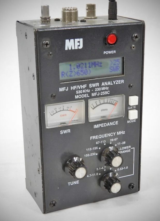
The MFJ-259C is a compact, battery-powered RF impedance analyzer designed to deliver comprehensive diagnostics for antenna systems and RF networks. Fully portable and self-contained, it functions as an essential bench and field tool for amateur radio operators and RF engineers.
The primary difference between the MFJ-259B and the MFJ-259C is that the "C" version extends the frequency coverage both up an down. The downward extension is accomplished with and additional control located under the main frequency band selector.
Features
– Frequency Coverage: Features an expanded-coverage internal VFO spanning 0.53 MHz to 230 MHz across nine overlapping bands (covering LF, HF, and VHF spectrums, including the AM broadcast band). (Note: It can be modified internally to shift LF coverage down to the experimental 630-meter band at 472–479 kHz).
– Internal Signal Generator: Generates a discrete RF stimulus signal outputting approximately 20 mW (3-Vpp / +5 dBm) into 50 Ohms via its SO-239 antenna port, with harmonics suppressed below -25 dBc.
– Display Interface: Equipped with a high-contrast two-line LCD display for precise digital readouts alongside two independent analog meters for real-time tracking of SWR and Impedance magnitude.
Primary Measurement Capabilities (Basic Menu)
By cycling through the unit's Mode button, you can access its core functionalities:
1 – SWR, R, X, and Z (Default Mode): Measures and displays five parameters simultaneously: Standing Wave Ratio (SWR), Resistance (R), Reactance (X), Impedance Magnitude (Z), and Phase Angle (θ).
2 – Coax Loss: Displays the real-time attenuation/loss in dB at any given VFO frequency for 50-Ohm coaxial lines, attenuators, or baluns.
3 – Capacitance (pF): Measures component reactance in Ohms and converts it mathematically into a capacitance reading in picofarads.
4 – Inductance (uH): Measures component reactance and calculates the corresponding inductance value in microhenries.
5 – Frequency Counter: Converts the device into a bench counter via a dedicated BNC input jack, featuring 3 selectable gate speeds (0.01s, 0.1s, 1.0s) to achieve resolution down to 100 Hz.
Advanced Engineering Metrics (Advanced Menu)
By pressing the Mode and Gate buttons simultaneously, the analyzer enters an advanced menu system designed for deep-dive transmission line analysis:
– Distance to Fault (DTF): Pinpoints physical cable issues, breaks, or lengths in feet by measuring consecutive reactance nulls and applying the transmission line's specific Velocity Factor (Vf).
– Resonance Mode: Changes the analog Impedance meter to display raw Reactance (X) directly. This allows you to visually map and locate precise frequencies where capacitive and inductive reactances cancel out (X=0).
– Return Loss & Reflection Coefficient (ρ): Displays engineering parameters directly proportional to SWR to measure forward vs. reflected wave relationships.
– Match Efficiency (η): Displays the percentage of transmitted forward power vs. reflected power present in a transmission system.
Important Operating Characteristics
– Calibration Plane: The hard-coded reference point for peak measurement accuracy sits directly at the unit's SO-239 RF connector. For highly accurate complex impedance data (R ± jX), it is recommended to hook the device directly to the load or use an electrical half-wave cable to minimize transmission-line phase rotation errors.
– Reactance Sign Ambiguity: Like most portable broadband analyzers, the unit measures the absolute magnitude of reactance but cannot natively calculate whether the sign is inductive (+jX) or capacitive (−jX). Users can verify the sign by tuning the VFO upward in frequency: if X increases, the load is inductive; if it decreases, it is capacitive.
– Diode Protection Warning: Because the high-frequency detector diodes are located right at the antenna port to maximize measurement fidelity, applying external voltages, connecting live transmitters, or failing to discharge static electricity from large ungrounded wire antennas can blow the sensitive detector diodes.
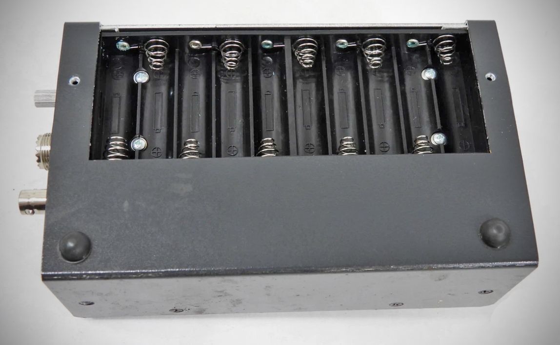
Power requirements: 11–16 VDC supply or 10 x AA batteries.
Draws roughly 220 mA during active testing.
Features a built-in internal trickle-charger circuit (selectable via an internal jumper plug for rechargeable Ni-MH/NiCd cells vs. non-rechargeable Alkaline batteries).
Includes an automatic Sleep Mode (Standby) that drops current draw to under 15 mA after 3 minutes of inactivity to conserve battery life.