Note
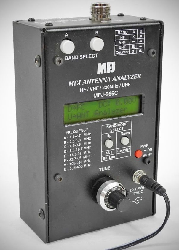
The MFJ-266(B)(C) is a self-contained, handheld RF diagnostic analyzer designed for both laboratory bench work and field testing. Weighing just over 1.3 pounds, it is engineered to be compact enough to fit comfortably in one hand. The versions are different only in minor circuit changes. They are functionally identical.
The unit operates primarily as a network analyzer utilizing an internal stimulus generator and a bridge circuit. It performs several diagnostic operations, displaying measurements on a backlit LCD screen:
– SWR: Measures standing wave ratios from 1:1 to 9.9:1.
– Impedance: Displays both Complex Impedance (Z = R + jX) and Impedance Magnitude (Z = ohms).
– Component Measurement (L/C Mode): Measures unknown capacitance (in pF, ranging from ~15 pF to 1200 pF) and unknown inductance (in µH).
– Frequency Counter: Functions as a 1 to 500 MHz frequency counter with selectable fast (1 kHz resolution) or slow (100 Hz resolution) gate speeds.
– Field Strength: Measures relative RF field strength in millivolts (mV).
– RF Signal Source: Generates a continuous carrier 2 dBm (2 mW) RF signal that can be utilized to test receivers, low-power amplifiers, networks, and antenna patterns.
Frequency Coverage & Tuning
– Band A: 1.5 to 2.7 MHz (160 Meters)
– Band B: 2.5 to 4.8 MHz (80/75 Meters)
– Band C: 4.6 to 9.6 MHz (60/40 Meters)
– Band D: 8.5 to 18.7 MHz (30/20/17 Meters)
– Band E: 17.3 to 39 MHz (17/15/12/10 Meters)
– Band F: 38.7 to 71 MHz (6 Meters)
– Band V: VHF band (108 to 230 MHz): Continuous coverage for Airband, 2 Meters, VHF 2-Way, and 1.2 Meters.
– Band U: UHF band (305 to 490 MHz): Continuous coverage for Military, 70-cm, and UHF 2-way. (Note: In the UHF range, only the SWR metric is displayed.)
Tuning is managed via an instrumentation-grade potentiometer linked to a 10:1 vernier drive reduction for smooth frequency adjustment. It also features a mechanical dial lock lever on the side of the knob to secure the chosen frequency.
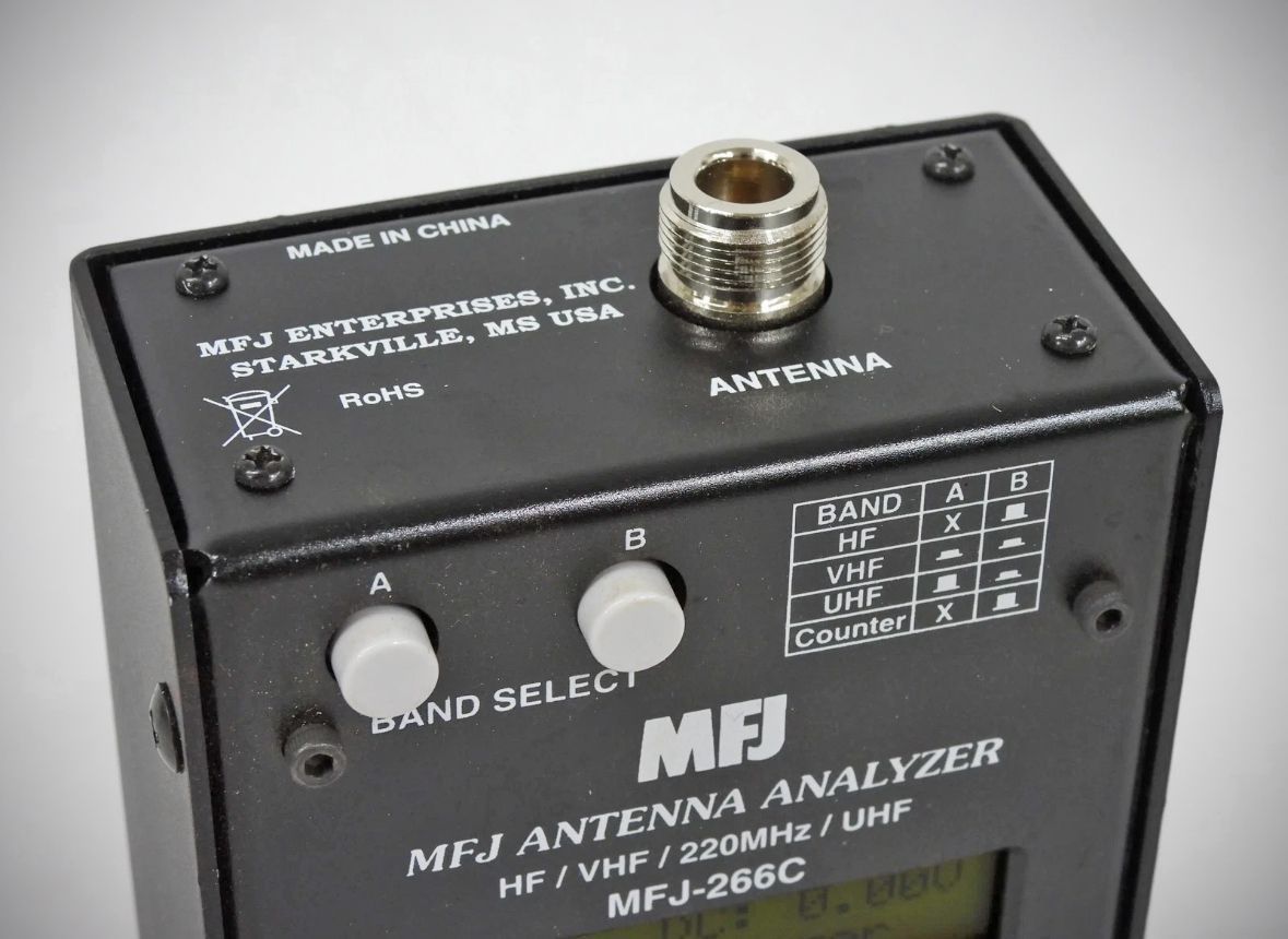
Antenna Connector: Features a female Type-N RF connector to ensure optimal signal continuity up to 500 MHz. It includes an N-male to SO-239 female adapter to accommodate standard PL-259 coaxial lines.
Power Requirements: The unit requires a power supply window between 3.5V and 5V when using battery configurations. It can be powered by:
– An internal 4-cell alkaline AA battery pack.
– An optional rechargeable internal 18650 Lithium-ion cell, which charges via a built-in circuit when connected to external power and turned off.
– A well-filtered external 12 to 15 VDC power supply (such as the MFJ-1312D).
Power Management: An internal `EXT PWR-BAT` jumper on the circuit board must be physically moved depending on whether battery power or an external DC source is used, as the unit cannot run on both concurrently. The operational current draw scales from 30 mA up to 180 mA depending on the active mode and display backlight usage.