Note
QST, May 1979, p. 148.
QST, Jan 1980 p. 124.
QST, Apr 1981, p. 116.
QST, Jan 1982 p. 190.
This is based on a construction project that appeared in the March 1979 issue of Popular Electronics--just two month before the commercial version was advertised in QST. Microcraft would soon be renamed Microlog.
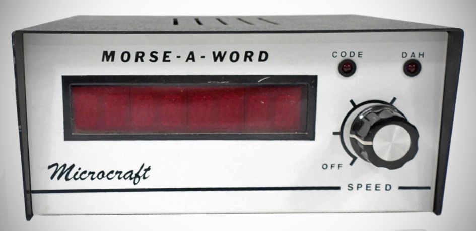
The Morse-A-Word is a code reader that automatically converts incoming dits and dahs into alphanumeric symbols for display on a multi-character LED readout. It allows users to sit back and read messages sent in CW, even if they do not know the code themselves. The device operates in a moving-character fashion, bringing new characters in from the right and moving existing ones to the left, which makes the messages easy to read. It is designed for use with communications receivers, telegraph keys, or code practice tape recorders, making it an excellent operating and code practice aid for both beginners and seasoned radio amateurs.
The Morse-A-Word II is a refinement of the original. The two versions are visually identical.
How it Works
1. Audio Filtering and Rectification
– Input: The audio output from a radio receiver is fed into an active bandpass filter that is centered at 800 Hz to isolate the Morse code tones.
– Processing: The filtered output is rectified and processed by an RC network and decoder, creating a low voltage when the key is down and a high voltage when the key is up. A low-pass filter then smooths this output.
2. Signal Digitization
– Squaring the Signal: A Schmitt trigger is used to square up and invert the smoothed signals.
– TTL Compatibility: This stage converts the analog tones into clean, TTL-compatible digital signals where a logic 1 represents a key-down (tone present) and a logic 0 represents a key-up (silence).
3. Counting and Timing
– Clocking: The digital signals are sent to two separate counters—one for key-up and one for key-down. These counters run at a rate determined by the adjustable code-speed clock on the front panel.
– Distinguishing Dits and Dahs: The key-down counter measures the duration of the tone. If it counts more than seven clock pulses, the circuit registers a "dah" and transfers a logic 1 to an eight-bit serial/parallel shift register. If the count is seven or less, it registers a "dit" and transfers a logic 0.
4. Character Assembly
– Element Spacing: When the key-up counter detects a short pause (less than eight clock pulses), it signals the shift register to accept the next dit or dah. The shift register is always initialized with the binary word 00000001 to ensure each Morse character is decoded properly.
– Character Completion: When the key-up counter detects a space longer than seven clock periods, the circuit recognizes the end of a character. The unique binary code in the shift register is then transferred to a latch for decoding.
– Word Spacing: If the key-up counter continues past 15 clock pulses, the circuit interprets this as a space between words and inserts a blank character.
5. Memory and Display
– Storage: A 16-element RAM stores the decoded Morse characters obtained from the latch.
– Readout: The RAM syncs with the eight-character display using an address counter and a ROM, which translates the binary data into the visual characters seen on the dual-character LED displays. This multiplexed circuit creates the right-to-left moving-character presentation.
Features
– Practice Aids: Includes a built-in code practice oscillator and monitor speaker.
– Noise Rejection: Features a sensitive input stage and a highly selective filter to help reject noise.
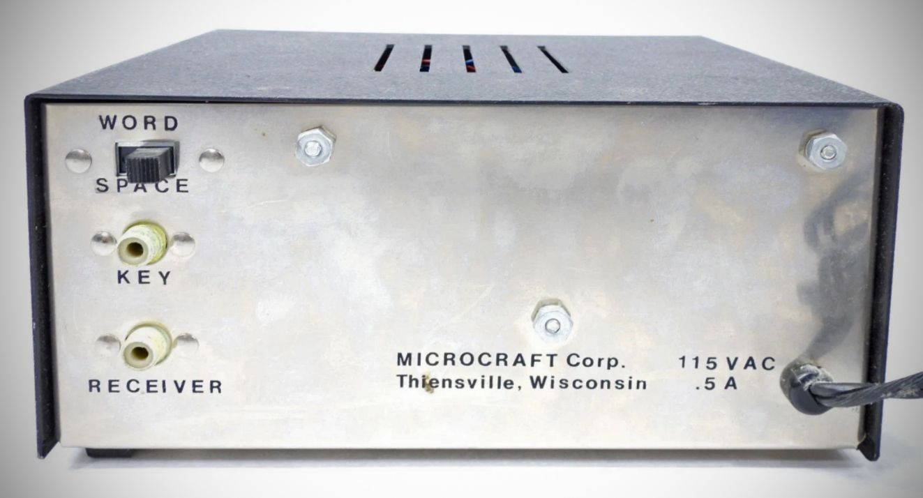
– Word Spacing: Includes a word space switch that can be utilized when receiving machine-sent code.
Specifications
– Speed Range: 5 WPM to 35 WPM, which can be adjusted via a front panel control.
– Speed Margin: Operates reliably within a 50 percent margin of the speed setting.
– Morse Characters Supported: Letters A-Z; Numbers 0-9; Question Mark; Comma; Period; Slant; and special characters AS, BT, AR, KN.
– Readout: Eight character, 14 segment alphanumeric display.
– Readout Type: Dual character IEE 3785R or equivalent, measuring 0.312 inches wide by 0.5 inches high.
– Receiver Input: RCA jack, 0.05 V minimum, 10 K ohms, with an internal CW filter centered at 800 Hz.
– Code Practice Input: RCA jack, ground to key oscillator/internal speaker.
Power Requirements: 117 VAC, 60 Hz, 20W (A 220 VAC, 50 Hz option was available).
Kit or wired.
MAWK-4 (4 character display), $149.95
MAWK-8 (8 character display), $169.95
References
Original construction article. Popular Electronics, Mar 1979, p. 35.
Brief description. Popular Electronics, Jul 1979, p. 10.