Note
QST, Dec 1950, p. 122.
QST, Mar 1952, p. 88.
Allied Radio catalog 1953 (copyright 1952), p. 69.
QST, Jun 1953, p. 101.
QST, Jan 1955, p. 137.
QST, Jan 1961. p. 145.
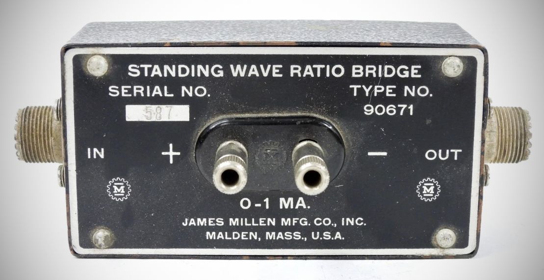
The Millen 90671 is an RF bridge is specifically designed to measure the standing wave ratio (SWR) in coaxial transmission lines. The device operates by comparing the resistance of an antenna and its transmission line against a fixed internal reference resistor.
Specifications
– Standard Impedance: 52 ohms (internal resistor R4 = 51 ohms)
– Optional Impedance: 75 ohms (requires replacing R4 with a 75 ohm resistor)
– Frequency Range: 1 to 15 MHz (high accuracy); up to 150 MHz (reduced accuracy)
– Extended Range: Up to 150 MHz with "good accuracy" if the RF choke is removed
– Required External Meter: 0 to 1 ma DC meter
– Rectifier Type: 1N34 crystal
Key Components & Design
– Bridge Arms: The ratio arms consist of accurately matched pairs: C2 plus R2 and C3 plus R3.
– Reference Resistor: The bridge compares the load to R4. While supplied at 51 ohms for 52-ohm lines, a 75-ohm spare is often soldered inside the base plate for conversion.
– RF Choke: Provided solely to offer a DC return path for "split radiator" type antennas.
– Regulation: Includes a coupling capacitor (C1) and a resistor (R1) to improve the regulation of the supplied RF power.
Operational Requirements
To use the bridge, a low-power RF source is connected to the input. The user must first adjust the power for a full-scale 1 ma reading with the output disconnected. Once the transmission line is connected to the "OUT" jack, the resulting meter reading is converted to an SWR value using the provided calibration curve.