Note
See National's notes: QST, Aug 1934, p. 69. (hints at new receiver)
QST, Oct 1934, pp. 72-73, inside back cover (first ad)
See National's notes: QST, Oct 1934, p. 61.
See National's notes: QST, Dec 1934, p. 69.
See National's notes: QST, Mar 1935, p. 77.
See National's notes: QST, Apr 1935, p. 75.
Also see QST, May 1935, pp. 21-28.
See National's notes: QST, Jun 1935, p. 61.
See National's notes: QST, Mar 1937, p. 63.
See National's notes: QST, Mar 1938, p. 67.
A few notes in QST, Sep 1941, p. 67.
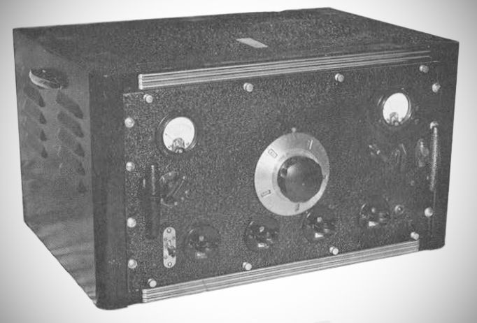
The HRO did not appear out of thin air. Instead, it was the culmination of a rapid and intense evolution over a short period between 1932 and 1934, adapting the company's earlier commercial and military contracts into the ultimate amateur radio operator's tool.
1. The Starting Point: The RHM Receiver (1931–1932)
The lineage began when the U.S. Department of Commerce selected the National Company to build ground-based airport and airway communications receivers. James Millen, with help from Herbert Hoover Jr.’s West Coast design team, engineered this first superheterodyne receiver was designated the RHM.
Because it was built for critical airport safety and navigation, the RHM established the "DNA" of what would eventually result in the HRO. Specifically, the use of plug-in coils: The RHM used sets of three individual plug-in coils (RF amplifier, mixer, and local oscillator) to cover different frequency bands. Millen felt strongly that it was not possible to achieve the lowest noise floor and high selectivity without the use of plug-in coils.
Another strand of the DNA included the micrometer dial to achieve high precision tuning.
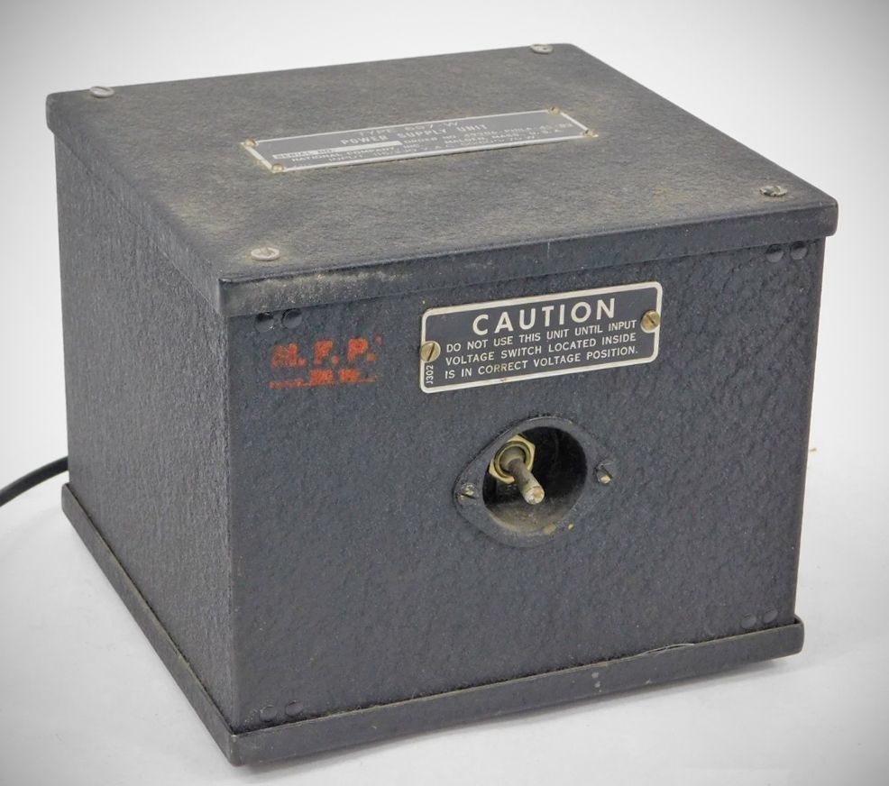
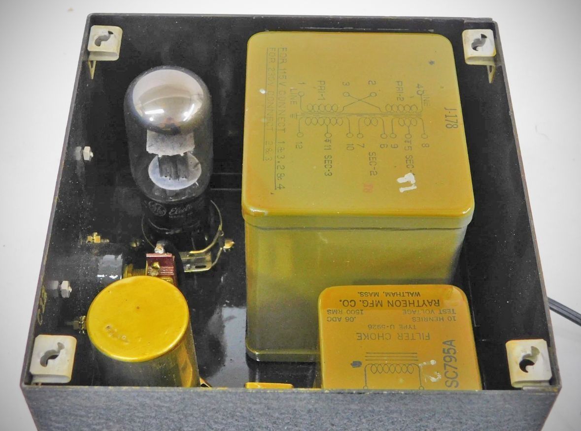
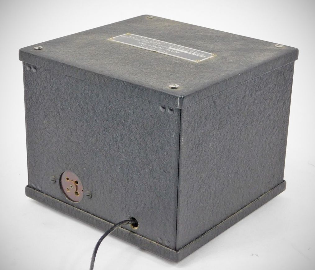
Yet a third piece in the genetics was an external power supply, to keep internal heat and electrical noise as low as possible.
2. Going Commercial: The AGS and AGS-X (1932–1934)
To capitalize on the prestige of the government contract, National modified the RHM design for commercial and amateur radio markets, naming it the AGS.
The AGS line served as a kind of proving ground for National. The receivers underwent rapid upgrades, culminating in the AGS-X "single signal" receiver in March 1933. The AGS-X introduced significant leaps forward that directly informed the HRO:
The AGS-X made use of advanced crystal filtering: It incorporated a James Lamb crystal filter and a front-panel beat frequency oscillator control, which drastically improved the operator's ability to isolate Morse code signals in crowded bands.
For more precise tuning, AGS also incorporated bandspread capability allowing an operator to stretch out a narrow amateur band across 100 divisions of the tuning dial.
3. Intermediate Stepping Stones: The RHP and RHQ
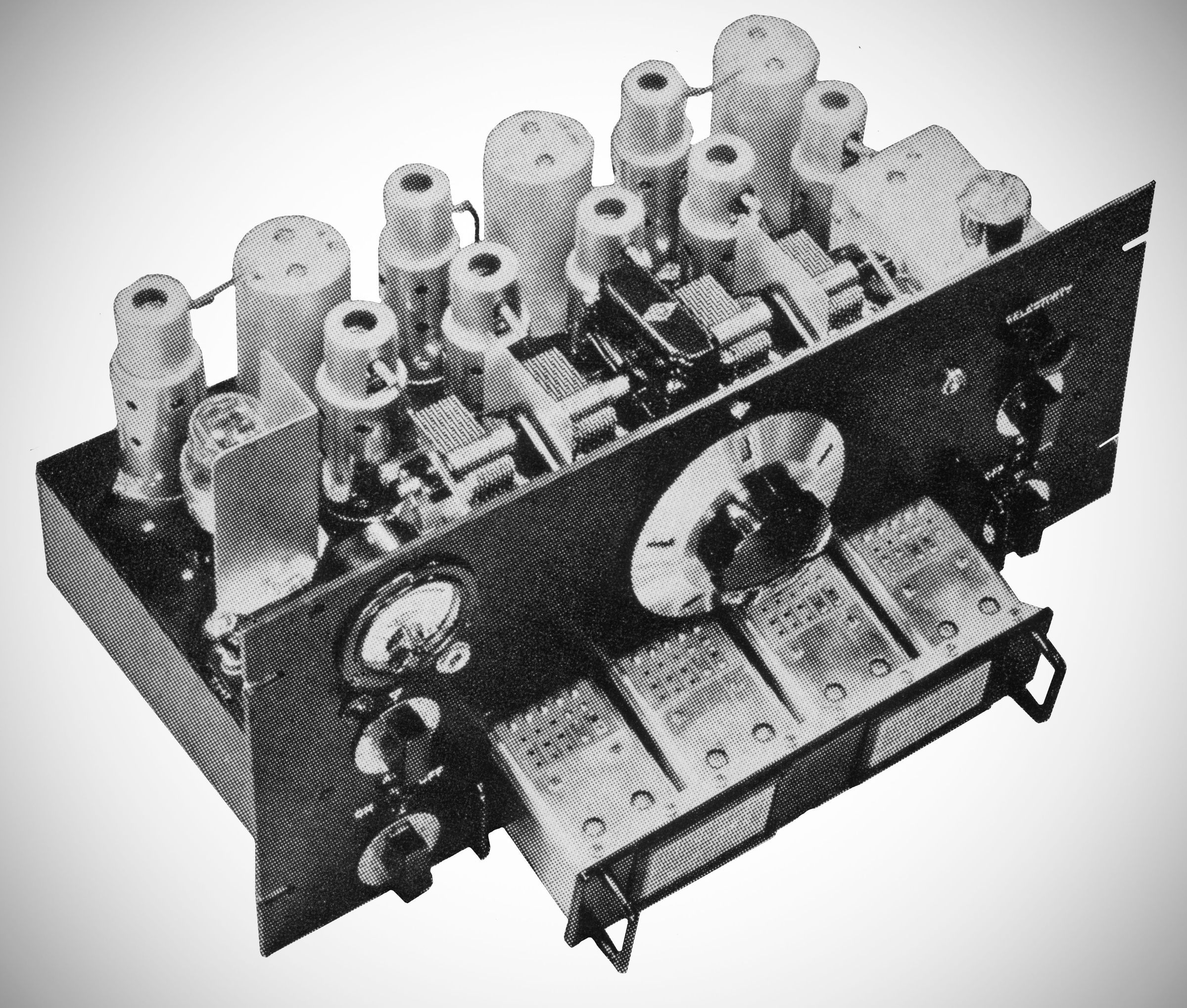
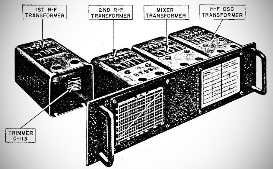
Alongside the AGS, National experimented with ergonomics via the RHP and RHQ models. Rather than making the operator plug in three separate coils manually for every band change, these experimental models ganged the three coils together behind a single panel. This created a unified, plug-in "coil set"—a concept that would become a defining physical characteristic of the HRO.
4. The Final Evolutionary Leap: The HRO (1934–1935)
With the release of the HRO, the AGS quickly became obsolete technology, but its architectural breakthroughs—individual plug-in coil shielding, high-precision micrometer tuning, and crystal filtering—provided the exact foundation National needed to build the HRO, widely considered "the cream of the crop" in communication receivers.
The HRO perfected and unified the AGS's earlier evolutionary traits, and they became the defining features of the HRO.
– The ultimate low-noise front end.
– The micrometer dial.
– The refined coils.
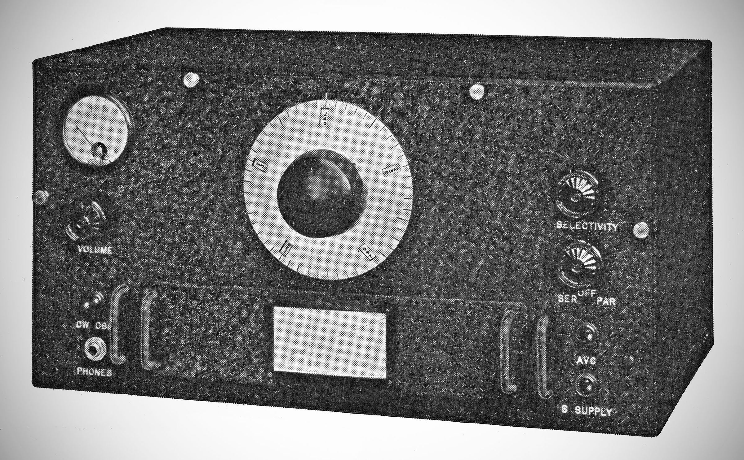
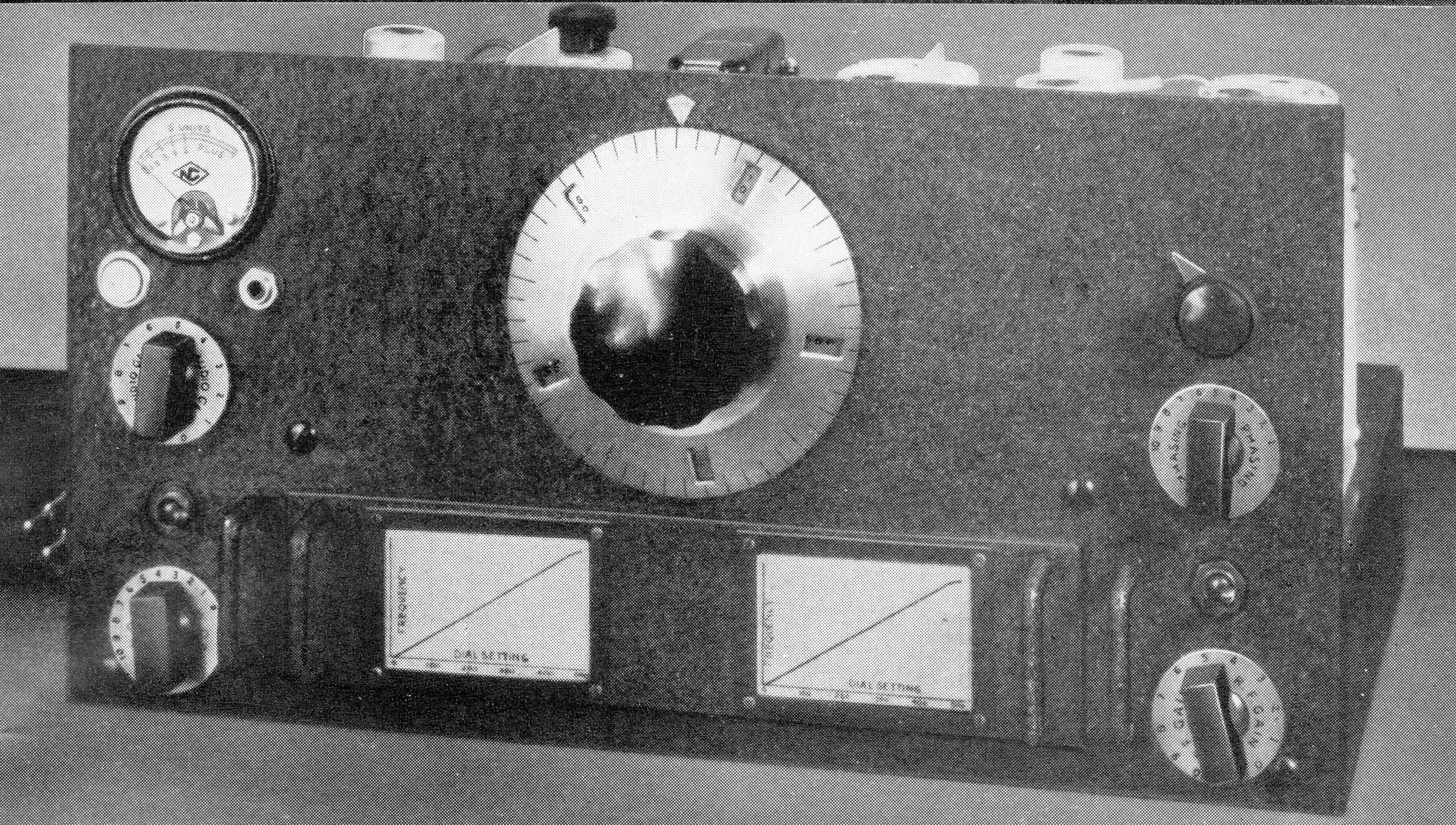
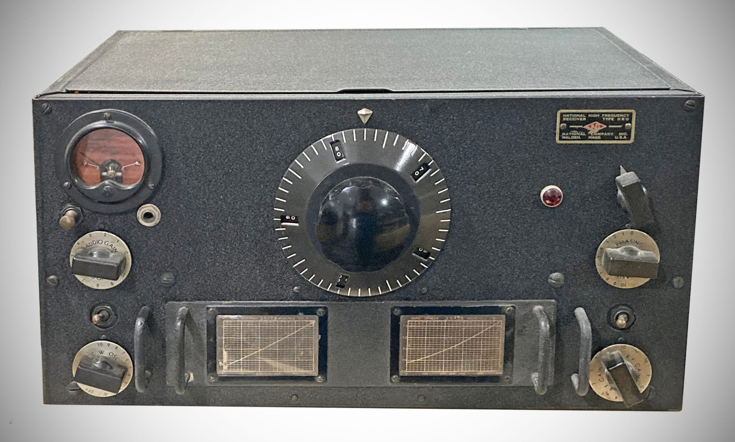
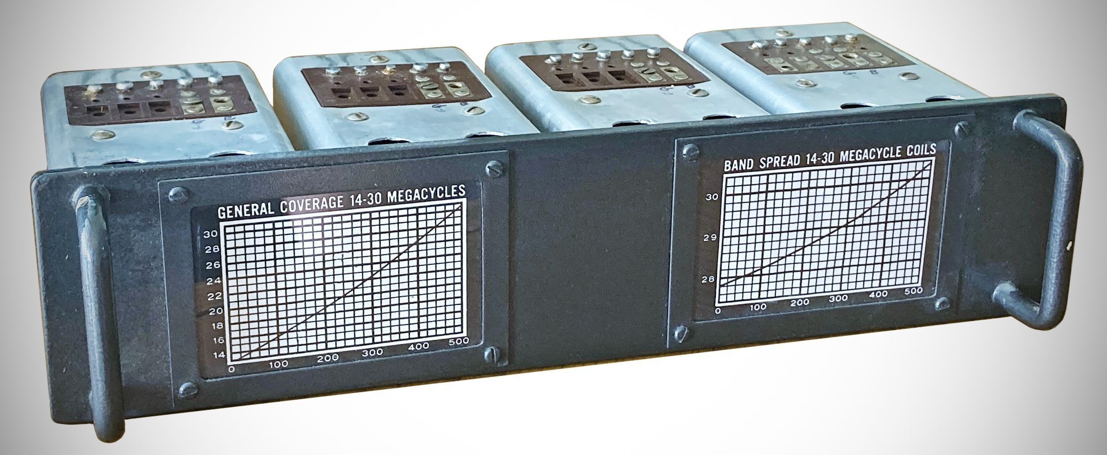
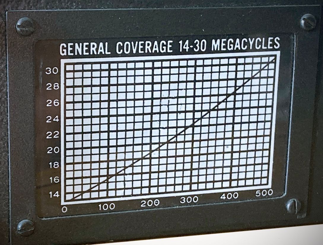
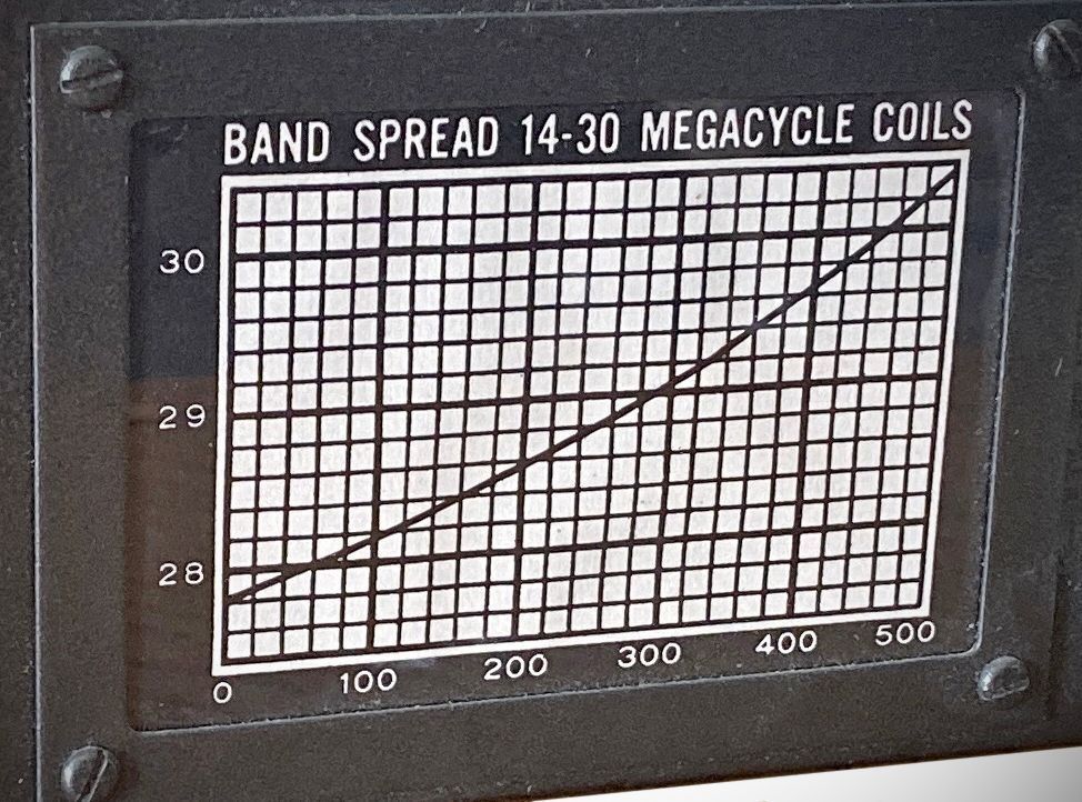
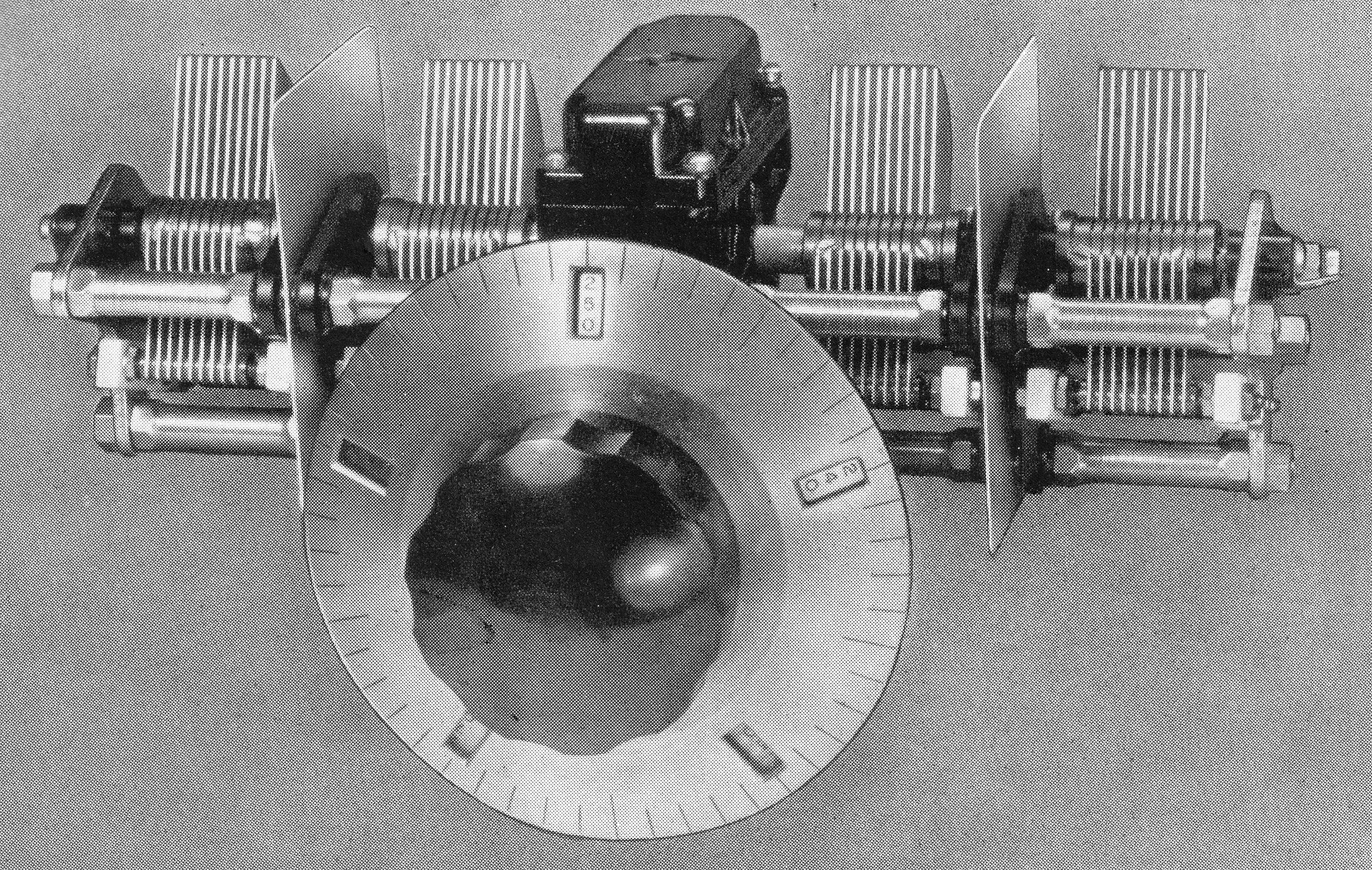
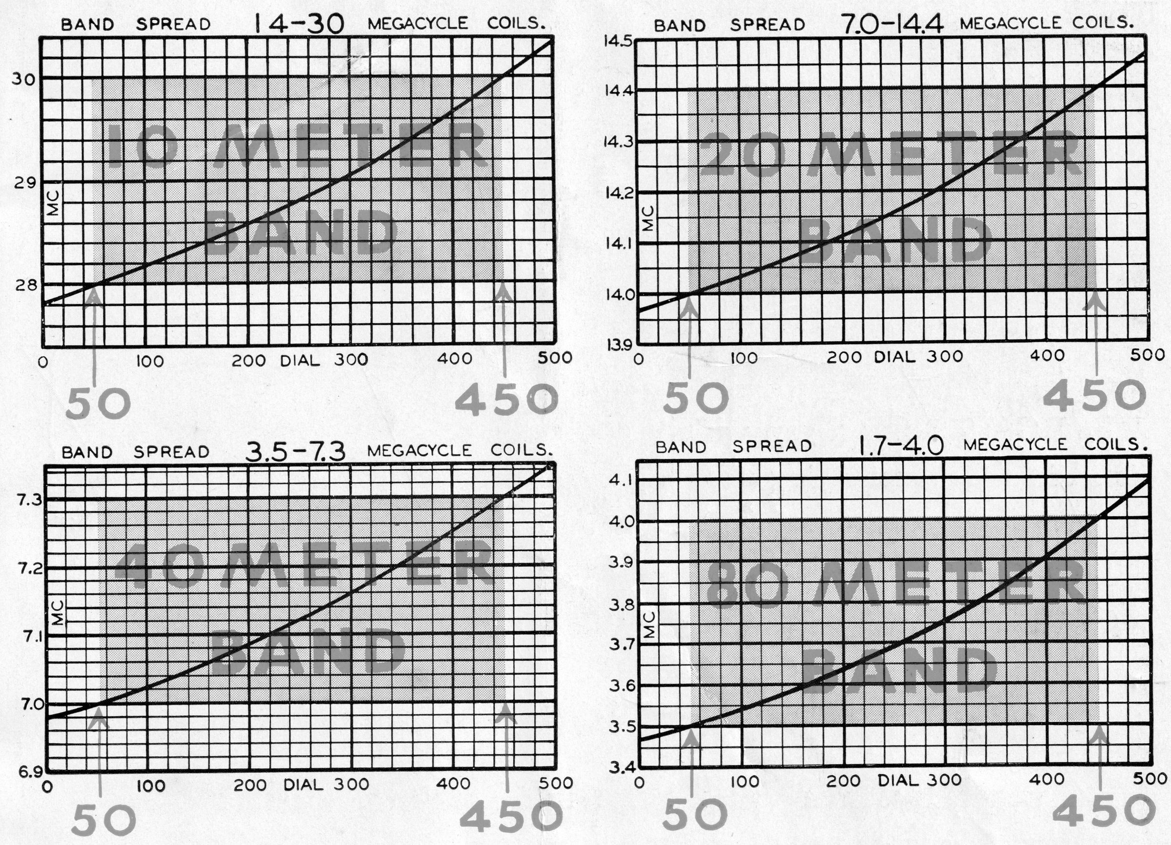
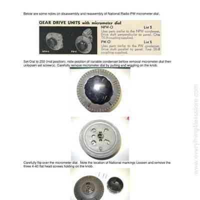
The micrometer dial reads direct to one part in 500. Division lines are approximately 1/4" apart. The dial revolves ten times in covering the tuning range, and the numbers visible through the small windows change every revolution to give consecutive numbering by tens from 0 to 500. The mechanism provides about 12 linear feet of tuning. The micrometer dial did not read the frequency directly. Instead, it acted as a linear logger, providing a numerical readout that could be correlated with a frequency chart on the plug-in coil set. The chart would indicate the operating frequency.
The micrometer dial rotated the tuning "condenser." The condenser was extremely rigid in construction, with four bearings on the rotor shaft. The drive, at the midpoint of the rotor, was through an enclosed preloaded worm gear with 20 to 1 ratio. Each rotor was individually insulated from the frame, and each has its own individual rotor contact. Stator insulation was steatite. The plate shape is straight-line frequency when the frequency range is 2:1.
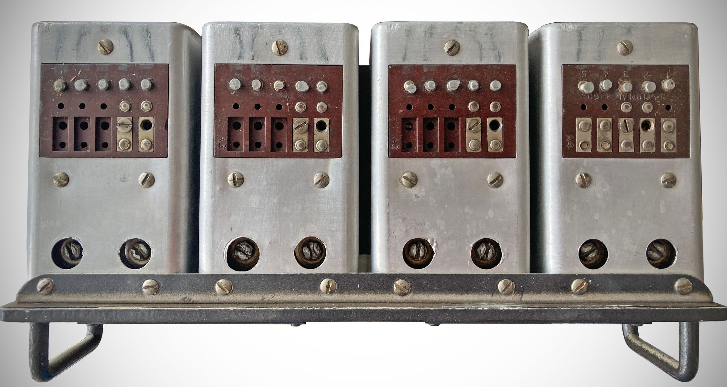
Changing bands involved removing a coil set from a drawer below the dial, and replacing with another. Several coil sets were available for different frequency bands. Each coil set, in turn, could be set for general coverage (left chart) or bandspread (right chart). This was accomplished by moving a small metal screw on a terminal block on each of the set's four transformers from on position to another. So, not a speedy process.
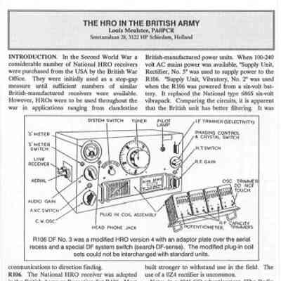
There were several iterations of the HRO, each introducing (generally) small changes in both physical appearance and electrical design, across many production runs. A total of between 8000–9000 units are though to have been manufactured between 1935 and 1941.
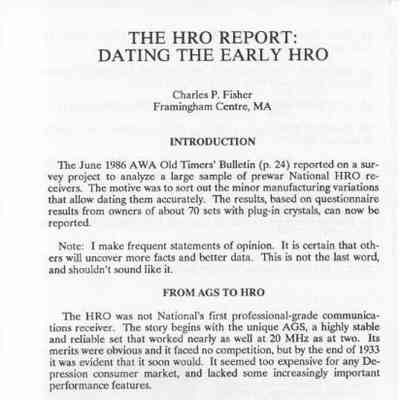
A superb analysis of the various models and changes can be found in the attached AWA article "The HRO Report," by Charles Fisher.
Specifications
– Sensitivity: 1.0 microvolt input (through IRE standard dummy antenna) to deliver 2.0 watts output with a 7000-ohm load.
– Signal-to-Noise Ratio: 16 dB at 5 microvolts (ratio of output with 30% modulation ON/OFF).
– Signal-to-Image Ratio: 1000 to 1 at 14 MHz.
– AVC Characteristic: Flat within ±10 dB between 1.0 and 100,000 microvolts.
– Maximum Undistorted Power Output: 1.5 Watts.
– CW Noise Equivalent: 0.2 microvolts.
– Standard Selectivity (Crystal Filter Off):
Ratio 2: 3.0 kHz bandwidth
Ratio 10: 7.5 kHz bandwidth
Ratio 100: 14.0 kHz bandwidth
Ratio 1000: 21.5 kHz bandwidth
– Single-Signal Selectivity (Crystal Filter In):
Maximum Selectivity: Effective total width of 200 cycles.
Minimum Selectivity: Effective total width of 2.5 kHz.
Frequency Coverage & Tuning
Standard Frequency Range: 1.7 to 30.0 MHz (split across 4 standard plug-in coil assemblies):
1.7 to 4.0 MHz
3.5 to 7.3 MHz
7.0 to 14.4 MHz
14.0 to 30.0 MHz
Additional Coil Ranges Available: 50 kHz to 2.05 MHz.
– Tuning Scale: Micrometer dial with a consecutively numbered calibration from 0 to 500 (10 revolutions for 180º condenser rotation), achieving an effective scale length of 12 feet.
– Band-spread Tuning: Uniform span of 400 dial divisions per amateur band (via adjustable terminal screws on the plug-in coil panels).
Audio & Interface Impedances
Antenna Input Impedance: Averages approximately 500 ohms (designed for doublet or single-wire antennas).
Output Impedance: 7000 ohms.
– Speaker Output Requirements: Capable of carrying the plate current of the output tube (~30 mA); dynamic speakers require an external field excitation source and a 7000-ohm built-in coupling transformer.
– Headphone Jack: Front-panel mounted, wired into the pentode section output of the 6B7/2B7 tube.
Power Requirements
115 VAC, 60 cycles
With Type 697 Pack: 0.6 amperes
With Type 5886 Pack: 0.4 amperes
– Type 697 Table Pack for 6.3 volt tubes, 230 volts, 75 m.a., with tube.
– Type 5886 AC Operation Pack for Battery Model for 6.3 volt tubes, 170 volts, at 50 m.a., with tube.
– Type 686 Table Pack for 6.3 volt tubes, 165 volts, at 50 m.a., with vibrator.
– Type GRSPU Single Pack, rack mount supplied with same characteristics as 697 or 5886, with tube.
– Type GRDPU Double Pack, rack mount same characteristics as GRSPU but with two separate and complete power supplies, with tubes.
– Battery Model Power Supply (Type HRO-B): Adjusted for a plate potential of 180 volts at a current drain of ~55 milliamperes.
230 volt AC. or 25 cycle operation also available.
Tube Lineup
Note: The HRO could be run with either 2.5 or 6.3 volt tubes.
2.5 volt 6.3 volt
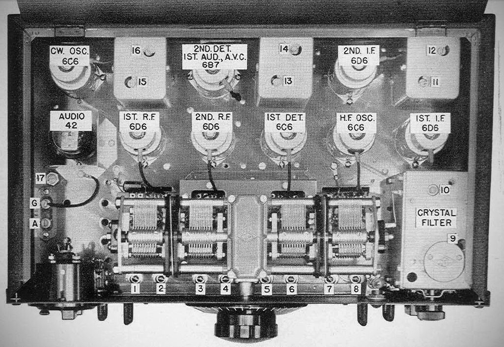
First R.F. 58 6D6
Second R.F. 58 6D6
First Detector 57 6C6
HF Oscillator 57 6C6
First I.F. 58 6D6
Second I.F. 58 6D6
Diode Detector, AVC, First Audio 2B7 6B7
Second Audio 2A5 42
Beat Frequency Oscillator 57 6C6
Variants
– HRO Standard AC table model, or HRO-B battery operated, complete with tubes and four sets of coils covering from 1.7 to 30 MHz, less speaker and power supply. List Price, $299.50
– HRO and HRO-B, same as above, but mounted on a 3/16" aluminum panel finished in either black leatherette or gray enamel for relay rack mounting. List Price, $320.00
– HRO Junior or HRO-B Junior, table model, with tubes and one set of 14 to 30 MHz coils, less speaker and power supply. List Price, $180.00 (see separate entry)
– HRO Junior models, same as above, but panel mounted similar to the rack model HRO. List Price, $200.00 (see separate entry)
Coil Sets
HRO Junior Coils ranges, General Coverage Only
JA 14-30 MHz
JB 7.0-14.4 MHz
JC 3.5-7.3 MHz
JD 1.7-4.0 MHz
HRO Bandspread coils: any standard short wave range.
Additional HRO Coils, General Coverage Only
J 50-100 KHz
H 100-200 KHz
G 175-400 KHz
F 500-1000 KHz
E 900-2050 KHz
Accessories
– MCS Table model metal cabinet and 8" P.M. Dynamic Speaker with 7000 ohm matching transformer.
– RFSH (speaker as above), rack mounted on 8¾" aluminum panel.
– SPC Combination 8" P.M. dynamic speaker, power supply (standard specifications) and coil storage compartment for five coils.
– MRR table relay rack, panel capacity 24½", gray or black as used with combination of HRO and SPC units.
– HCRP Rack mounted coil storage compartment for five HRO coils.
References
Review. Radio News, Sep 1935, p. 150.
Review. Radio News, Oct 1935, p. 208.
Discussion. Radio News, Jan 1936, p. 398.