Note
Announced QST, Aug 1964, p. 107. Will be shown at Wescon in LA.
QST, Oct 1964, inside back cover.
QST, Feb 1965, p. 105.
QST, Apr 1965 p. 129.
QST, Feb 1966, back cover.
CQ, Jun 1968, p. 121.
QST, May 1969, p. 127.
Hamtronics ad: "National is back." First seen QST, Nov 1976, p. 131.
QST, Jan 1977, p. 147.
The HRO-500 makes a comeback? Along with NCX-1000 and NCL-2000.
The ads ran until May 1977.
"P" version is portable.
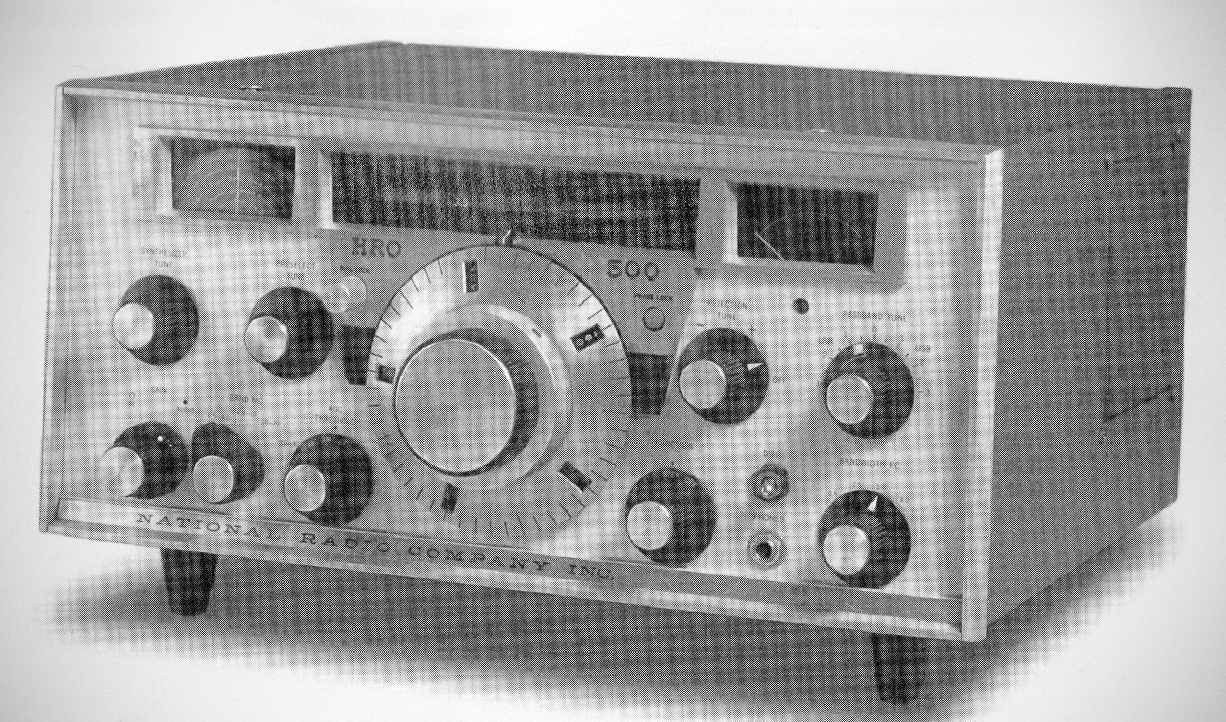
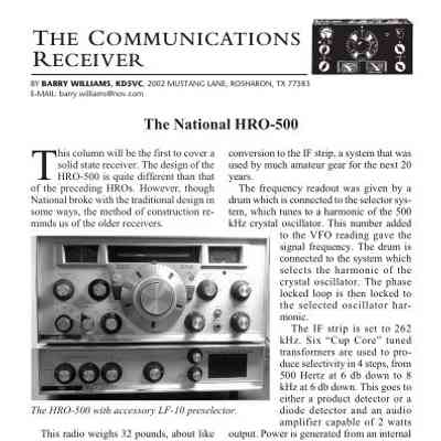
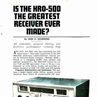
Three decades after the production of the first HRO model, National introduced their HR0-500. Only the trademark PW dial remained as a constant. Everything else about the famous receiver line had changed. The HR0-500 was all-solid-state and synthesized. It covered 5 kHz – 30 MHz in sixty 500 kHz bands. The VFO's tuning rate was identical on all bands. A tunable six-pole filter provided selectivity bandwidths of 0.5, 2.5, 5.0, and 8.0 kHz. Passband tuning was used on the 0.5 and 2.5 kHz positions. Its rejection tuning featured a 60 dB notch. It operated from either 115/230 VAG or 12 VDC power.
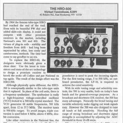
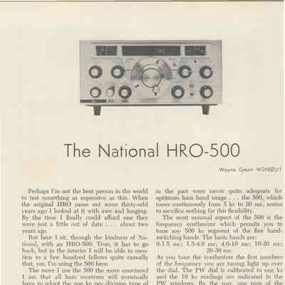
Introduced by the National Radio Company around 1964 to replace the legendary tube-type HRO-60, the HRO-500 was designed as a high-end, state-of-the-art solid-state receiver aimed primarily at the commercial market. It represented a clean-slate design intended to compete directly with premium brands like Collins.
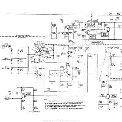
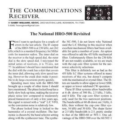
Moving away from traditional plug-in coils, the HRO-500 uses a frequency synthesizer driven by a high-frequency voltage-controlled oscillator (VCO) phase-locked to a 500-kHz crystal standard. The synthesizer generates 60 stable frequencies spaced 500 kHz apart.
To optimize image rejection, it uses triple conversion for frequencies below 4 MHz and double conversion for frequencies above 4 MHz.
It features a sharply tuned six-pole IF filter offering four selectable bandwidths: 8.0, 5.0, 2.5, and 0.5 kHz. The two narrowest ranges can be varied over +–3 kHz. It also includes a tunable notch filter centered around the receiver IF that provides 50 dB of attenuation over a ±10 kHz window.
To manage varied signal strengths from weak DX to strong local shortwave broadcasts, the AGC threshold can be stepped in three 10-dB increments. It features separate AM and product detectors.
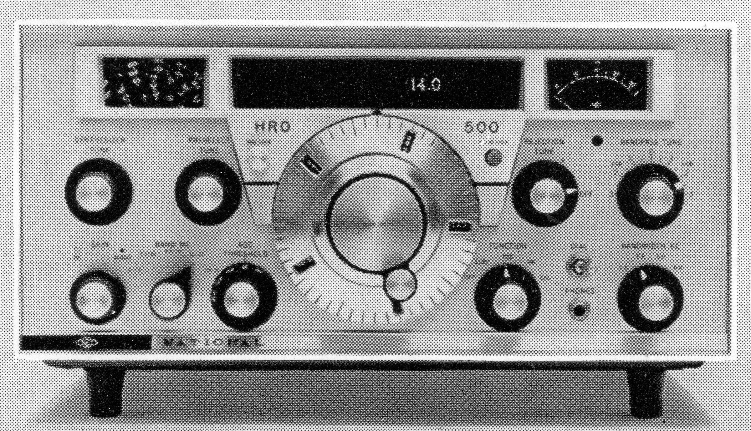
The front panel is anchored by National’s iconic PW dial assembly. Early variants included a spinner knob, while later production runs moved to a flared-skirt knob with a raised flange for rapid spinning and a center vernier adjustment.
The interface features three distinct windows: the left window displays the preselector frequency, the center shows the synthesizer's 500-kHz starting range, and the right functions as the S-meter.
Accessories
LF-10 Preselector: On the lowest tuning range (5 to 500 kHz), the internal preselector is bypassed, and the outboard LF-10 preselector unit is required to meet rated sensitivity. The LF-10 sits directly beneath the receiver, draws its power from the HRO-500, and includes an additional RF filter and a built-in monitoring speaker.
Other Options: National also offered a matching standalone speaker (the 500TS) and a dedicated rack-mounting kit.
Because they were sold at a premium price to a mostly commercial clientele, HRO-500s are relatively rare and highly prized by collectors today. However, they are notoriously difficult to service due to the extensive internal shielding—making even simple maintenance, like replacing a dial bulb, a technical challenge.
In 1977, long after the HRO-500 had been discontinued, Hamtronics somehow acquired a number of HRO-500s as new-old-stock, and ran an ad proclaiming "National is Back." QST, Nov 1976, p. 131. The ad also listed the NCX-1000 and NCL-2000 and ran until May 1977.
Specifications
– Frequency Range: 5 kHz to 30 MHz continuous in 60 500-kHz bands.
– Modes of Operation: SSB, AM, CW, FSK, FAX.
– Frequency Tuning: Synthesizer continuously variable in 60 500-kHz bands; main tuning linear VFO covering 500 kHz.
– Dial Calibration: Synthesizer in 500-kHz steps; main tuning 1.0 kHz; dial accuracy better than 1.0 kHz over entire range.
– Frequency Stability:
– Overall Drift: 300 hertz per hour to two hours after turn-on; less than 100 hertz/day thereafter.
– Voltage Drift: Less than 100 hertz/day for 40-volt change in AC input voltage.
– Temperature Drift: 50 hertz per degree C.
– Sensitivity (500 kHz to 30 MHz):
– SSB/CW: Better than 1.0 microvolt for 10 dB $S+N/N$ ratio.
– AM: Better than 2.0 microvolts for 10 dB $S+N/N$ ratio.
– Sensitivity (5 kHz to 500 kHz):
25 to 50 microvolts without preselector.
Better than 2.0 microvolts for 10 dB S+N/N ratio with optional LF-10 preselector.
– Selectivity (at 6 dB points):
500 Hz (0.5 kHz)
2.5 kHz
5.0 kHz
8.0 kHz
– Shape Factor (6 to 60 dB): 2.5:1 nominal in 2.5-kHz position.
– Passband Tuning: Continuously variable in 500-Hz and 2.5-kHz bandwidth positions.
– Heterodyne Rejection: 50 dB minimum notch depth.
– Image Rejection: Greater than 50 dB over entire range.
– IF Rejection: Greater than 60 dB.
– Internal Spurious: All less than 2.0 microvolts equivalent input except discrete responses at 2.75 MHz and 3.0 MHz.
– AGC Characteristics: Change in audio output less than 5 dB for input signal change from 10 to 100,000 microvolts.
– AGC Threshold: Front panel selectable attenuation of 0, 10, 20, or 30 dB.
– Audio Output: 2.0 watts maximum into 3.2-ohm speaker or 600-ohm balanced center-tapped line.
– Antenna Inputs: 50-ohm unbalanced (SO-239), high-impedance, and low-frequency VLF input.
– Semiconductor Complement: 37 transistors, 21 diodes, 1 zener diode regulator.
Power Requirements:
117/234 volts AC, 50-60 Hz, 15 watts (dial lamps off), 22 watts (dial lamps on).
11-16 volts DC, 200 mA at 50 mW output, 750 mA at 2.0 watts output.
References
Brief description. Popular Electronics, Jan 1965, p. 26.
Brief description. Electronics World, Feb 1965, p. 94.
Review. Popular Electronics, Aug 1965 p .45.
See National's notes: QST, Oct 1964, p. 111.
See National's notes: QST, Nov 1964, p. 87.
See National's notes: QST, Dec 1964, p. 115.
See National's notes: QST, Feb 1965, p. 93.
See National's notes: QST, Apr 1965, p. 109.
See National's notes: QST, Jun 1965, p. 119.
See National's notes: QST, Sep 1965, p. 113.
See National's notes: QST, Jan 1966, p. 99.
See National's notes: QST, May 1966, p. 105.
See National's notes: QST, Aug 1966, p. 97.