Note
QST, Jul 1952, inside back cover.
See notes from National: QST, Aug 1952, p. 71.
Allied Radio catalog 1953 (copyright 1952), p. 37.
QST, Apr 1954, p.111.
QST, Nov 1954, p. 160. (NC-98SW, with band spread for the 17, 19, 25, 31, and 41 meter bands.)
Walter Ashe catalog 1957 (probably issued in 1956), p. 2. (list of coils)
QST, Nov 1958, p.199.
QST, Jan 1960, p. 145.
QST, Dec 1963, inside back cover.
QST, Jan 1964, inside back cover.
QST, Oct 1964, p. 111. (note the "In recent years..." comment)
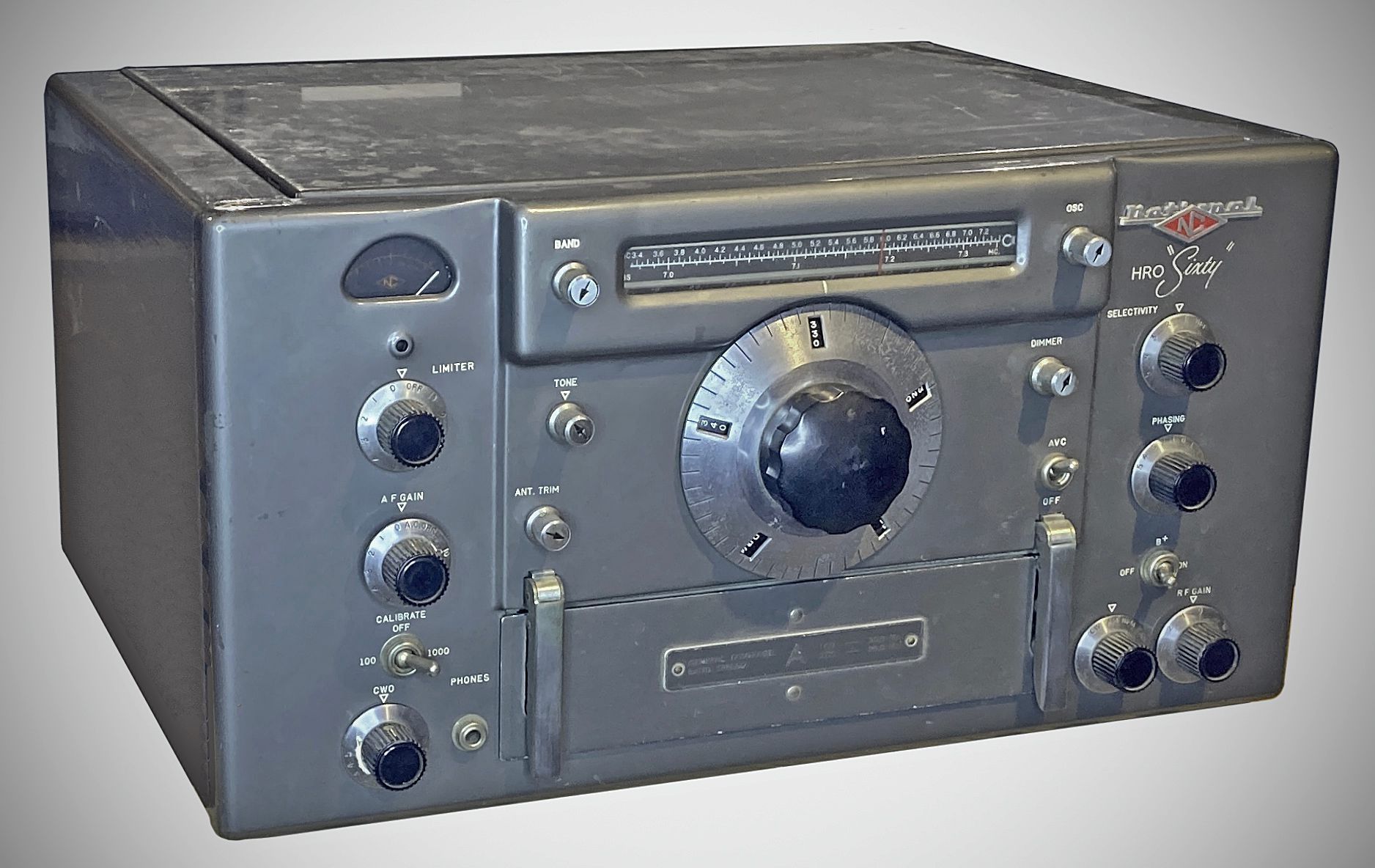
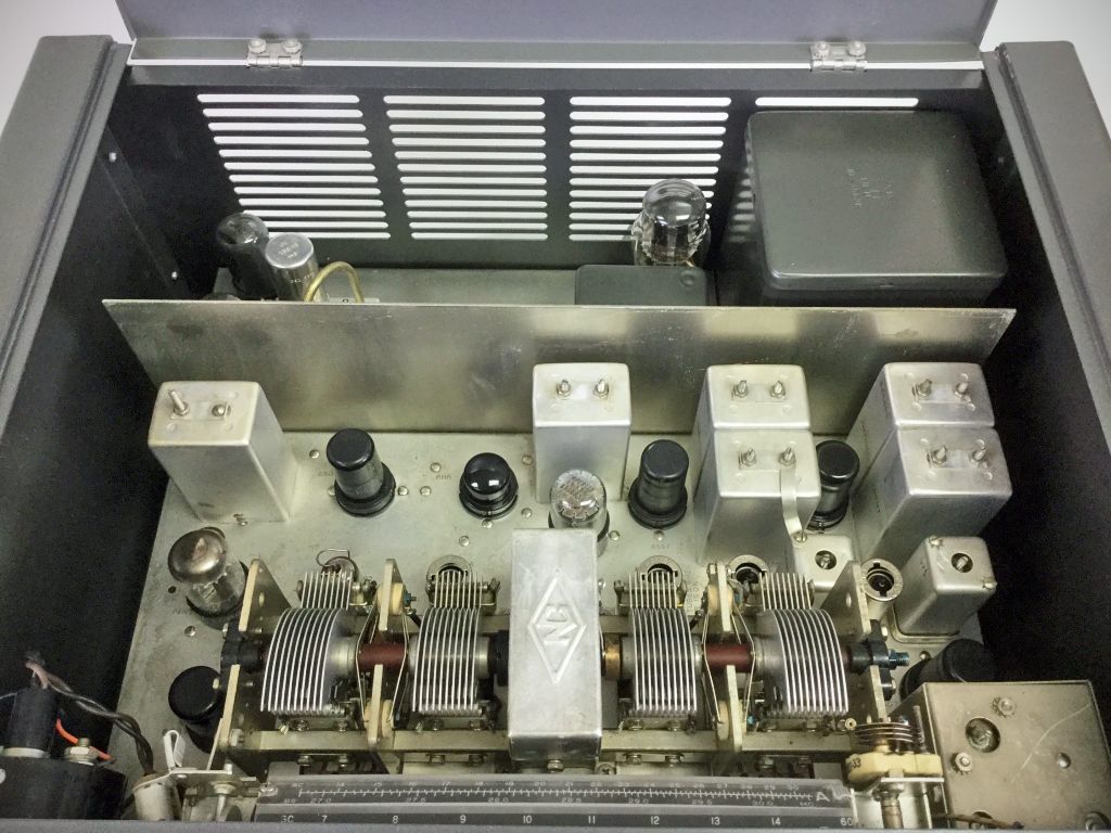
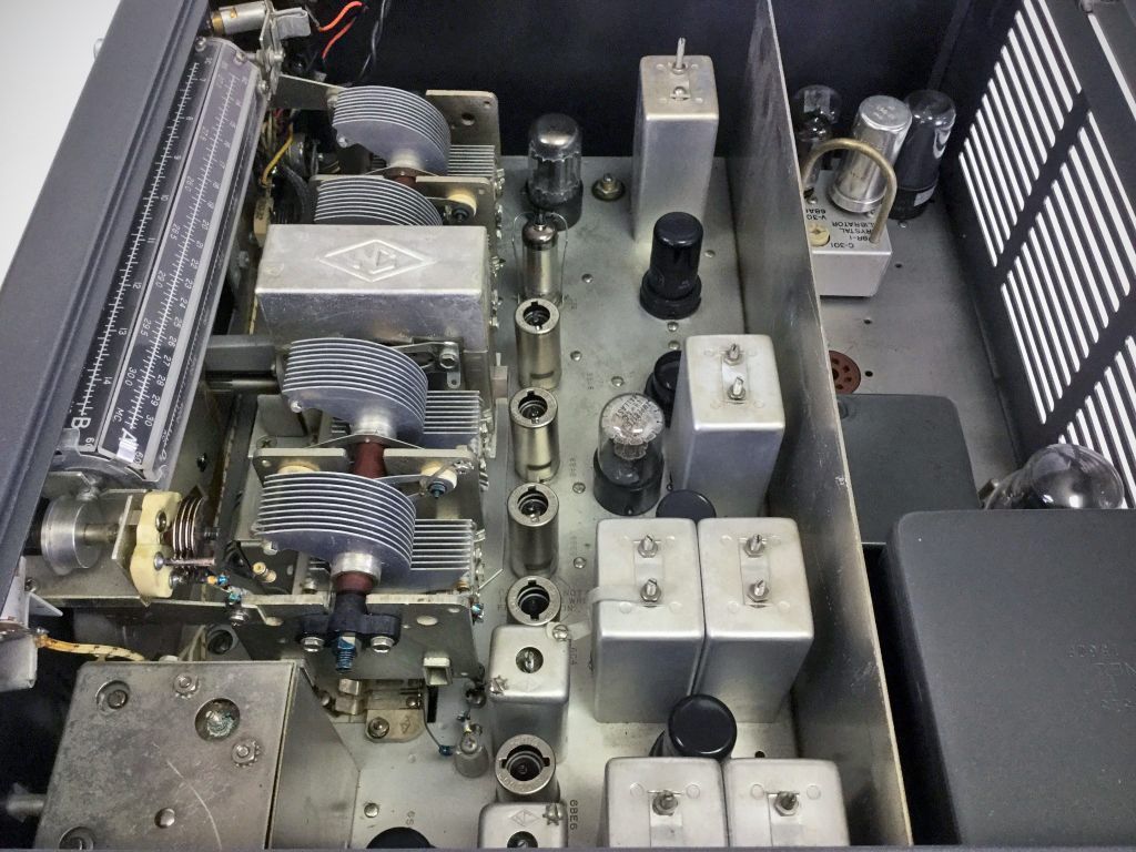
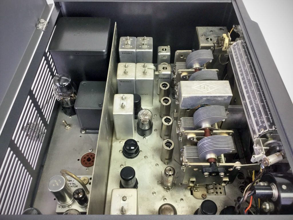
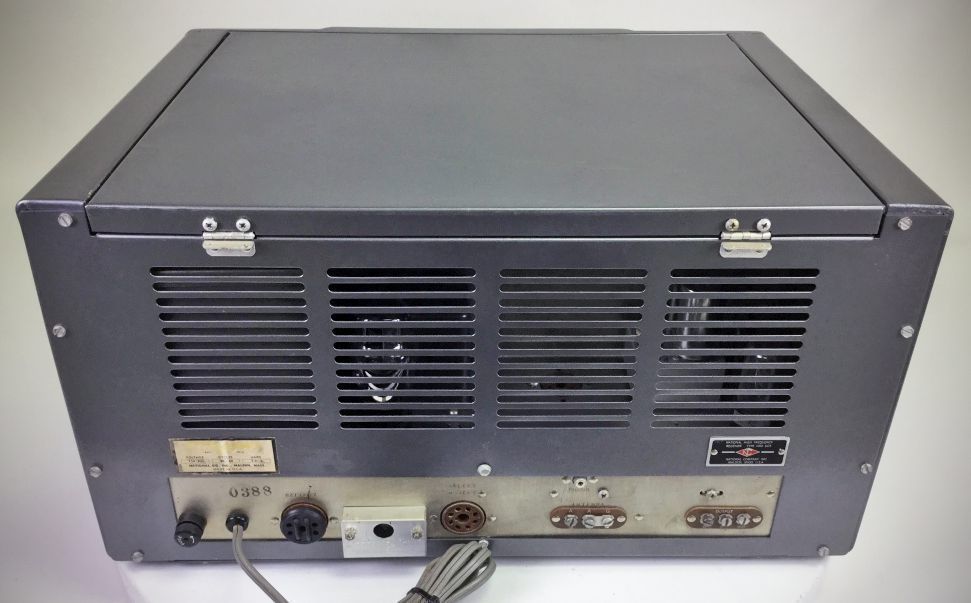
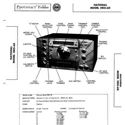
The HR0-60 was the final vacuum tube HRO. It broke new ground as the long-running receiver series continued to evolve. It introduced double conversion to the HRO line and used 18 tubes. Thirteen coils gave it a 50 kHz to 54 MHz tuning range. Matching speaker is the HRO-60TS (table top). Also available in rack mount as the HRO-60RS.
Features
– Dual Superheterodyne Circuitry: Utilizes a highly selective single-conversion circuit below 7,000 kHz, and automatically switches to a dual-conversion configuration with a 1990 kHz first intermediate frequency above 7,000 kHz for superior image rejection.
– Micrometer Dial Mechanism: Employs National's classic, heavy-duty micrometer dial-driving mechanism for precise, smooth, and highly accurate main tuning control.
– Dual-Scale Slide-Rule Dial: Features an illuminated main slide-rule dial that provides direct megacycle calibration for General Coverage coil sets, paired with dedicated bandspread scales for bandspread-capable sets.
– Front-Panel Oscillator Trimmer: Includes an adjustable front-panel trimmer control to maintain exact calibration accuracy across different coil configurations.
– Advanced Electrical Stabilization: Minimizes frequency drift through comprehensive temperature compensation, ceramic brush-board and coil-set insulation, active voltage regulation of the oscillator/mixer plate supplies, and active current regulation of their filaments.
– Six-Position Crystal Filter: Features a high-selectivity 455 kHz crystal filter offering six selectable positions of variable bandwidth to cut through dense adjacent-channel interference.
– Double-Action Noise Limiter: Features a fully adjustable, double-acting series-diode automatic noise limiter designed to severely reduce high-amplitude impulse noise and static crashes.
– Four-Position Mode Selection: A single master front-panel switch smoothly controls selection between CW., AM, Narrow-band FM, and Phono operating configurations.
– Push-Pull Audio System: Utilizes a built-in output transformer paired with a dedicated push-pull beam-power audio amplifier stage to ensure clean, high-fidelity audio response and distortion-free power output.
Specifications
– Frequency Range: 50 kHz to 430 kHz, and 480 kHz to 54.0 MHz across 13 plug-in coil sets
– Modes: CW, AM, NFM (Narrow-Band FM with optional NFM-83-50 adapter), and Phono (External audio input)
– Tuning Mechanism: 50-division micrometer-style dial driving a worm-gear assembly with a 20:1 reduction ratio, spanning an effective 12-foot linear scale across 10 full turns; paired with an illuminated slide-rule master frequency dial.
– Receiver Circuit Design:
Below 7.0 MHz: Single-conversion superheterodyne circuit.
Above 7.0 MHz: Double-conversion superheterodyne circuit (automatically engaged via a conversion mechanical slide switch on the plug-in coil assembly).
– Intermediate Frequencies:
First I.F. (High Bands only): 1990 kHz
Second I.F. (All Bands): 455 kHz
– RF Preselection: Two fully tuned, independent stages of radio frequency amplification on all bands to maximize image rejection and signal-to-noise ratio.
– Sensitivity: Better than 1.7 uV across the 2.0 MHz to 30.0 MHz range for a 10 dB signal-to-noise ratio.
– Selectivity: Controlled via a 6-position Crystal Filter network operating at the 455 kc I.F. stage, providing adjustable bandwidth from about 15 kHz to 400 Hz
– Antenna Input: Balanced or unbalanced 50 to 300 ohms (nominal ~500 ohms average across total coverage, rear panel screw terminals (ANT / GND)
– Audio Output (Speaker): 8 ohm and 500 ohm taps, rear panel terminal strip
– Headphones: Low to high impedance headphones, front panel 1/4" phone jack (disconnects final stage audio power output when inserted)
Accessory Provisions:
– Internal pre-wired sockets for XCU-50-2 (or XCU-60-2) Crystal Calibrator and NFM-83-50 FM adapter.
– Rear octal socket for external interface attachments like the SOJ-3 Select-O-Ject audio filter or an external Type 650S 6-Volt DC vibrator power supply for emergency/mobile deployment.
Power Requirements:
Built-in power supply configurable for 115V or 230V AC, 50-60 Hz.
Optional 650S 6-Volt DC vibrator power supply
Coil Set General Coverage Bandspread
A 14.0 - 30.0 MHz. 27.0 - 30.0 MHz.
B 7.0 - 14.4 MHz. 14.0 - 14.4 MHz.
C 3.5 - 7.3 MHz. 7.0 - 7.3 MHz.
D 1.7 - 4.0 MHz. 3.5 - 4.0 MHz.
E 900 - 2050 kHz. —
F 480 - 960 kHz. —
G 180 - 430 kHz. —
H 100 - 200 kHz. —
J 50 - 100 kHz. —
AA — 27.0 - 30 MHz.
AB — 25 - 35 MHz.
AC — 21.0 - 21.5 MHz.
AD — 50 - 54 MHz.
(Note: not compatible with HRO-50 coil sets)
Tube Lineup
V1 6BA6 1st R.F. Amplifier
V2 6BA6 2nd R.F. Amplifier
V3 6BE6 1st Frequency Converter
V4 6C4 High Frequency Oscillator
V5 6BE6 2nd Frequency Converter
V6 6SG7 1st I.F. Amplifier
V7 6SG7 2nd I.F. Amplifier
V8 6SG7 3rd I.F. Amplifier
V9 6H6 2nd Detector / A.V.C.
V10 6H6 Noise Limiter
V11 6SJ7 1st A.F. Amplifier
V12 6SN7GT S-Meter Amplifier / Phase Inverter
V13 6V6GT Audio Output (Push-Pull)
V14 6V6GT Audio Output (Push-Pull)
V15 6SJ7 Beat Frequency Oscillator
V16 5V4G Rectifier
V17 0B2 Voltage Regulator
V18 4H4C Current Regulator (Ballast)
References
Making 15 Meter Coils. CQ, Jan 1964, p. 52.