Note
QST, Jan 1963, inside back cover.
QST, Dec 1963, inside back cover.
QST, Jan 1964, inside back cover.
Allied Radio catalog 1965 (copyright 1964), p. 328.
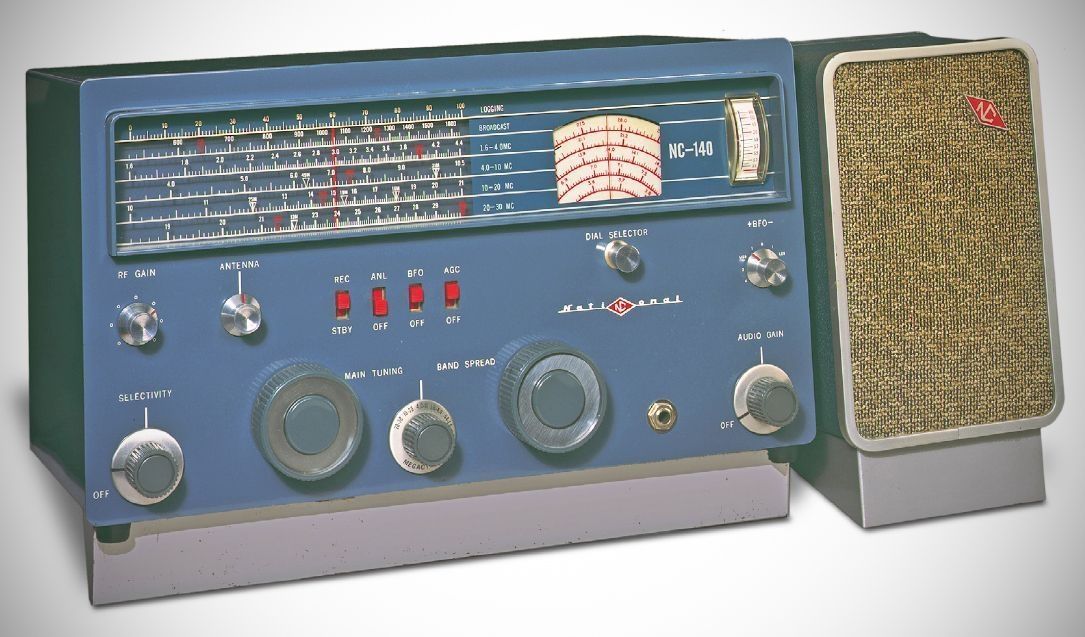
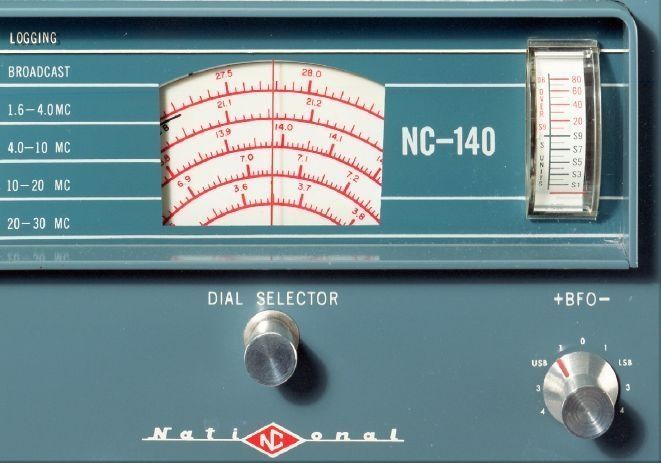
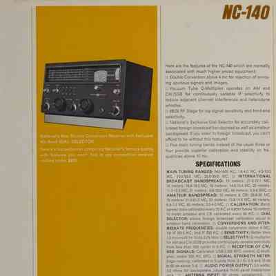
When the NC-140’s Dial Selector knob was pulled out and rotated a half-turn, the band-spread dial calibration changed from shortwave broadcast to amateur band frequencies, or vice versa. The general-coverage range of the receiver was 0.54–30 MHz in five bands. The eight-tube, double-conversion receiver used a Q-Multiplier in its 230 kHz second IF to aid selectivity.
Closely related to the NC-190. See discussion below.
Features
– Double Conversion: Operates as a double-conversion receiver on frequencies above 4 MHz to provide rejection of spurious signals and images.
– Q-Multiplier: Operates across AM, CW, and SSB modes, delivering continuously variable IF selectivity to cut down on adjacent channel interference and heterodyne whistles.
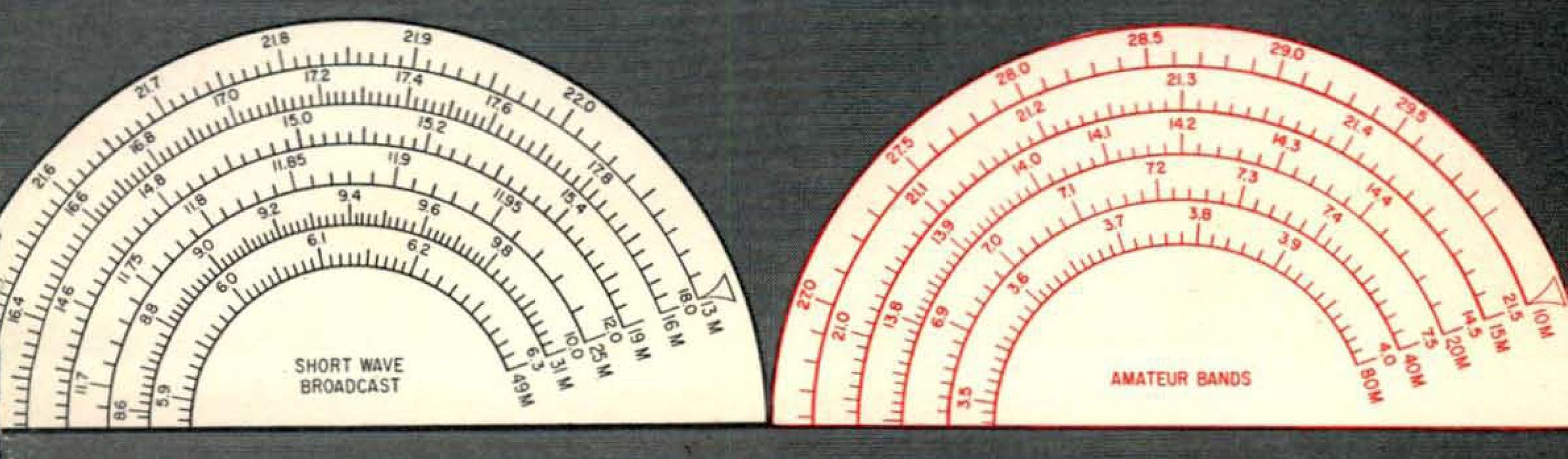
– Dial Selector: Mechanically alternates between two distinct groups of bandspread scales visible in the window—one for amateur bands (marked in red) and one for foreign international broadcast bands (marked in "midnight blue").
– Five Main Tuning Bands: The NC-140 uses five distinct main tuning bands to offer enhanced calibration and stability on frequencies higher than 10 MHz.
Specifications
Frequency Coverage: 540 kHz to 30 MHz
International Broadcast Bandspread:
13m (21.5 – 22.1 MHz)
16m (16.4 – 18.0 MHz)
19m (14.6 – 15.4 MHz)
25m (11.7 – 12.0 MHz)
31m (8.6 – 10.0 MHz)
49m (5.9 – 6.3 MHz
Amateur Bandspread:
10 meters & CB (26.6 – 30 MHz)
15 meters (21.0 – 21.5 MHz)
20 meters (13.8 – 14.5 MHz)
40 meters (6.9 – 7.5 MHz)
80 meters (3.5 – 4.0\ MHz
Intermediate Frequencies:
1st IF, 2215 kHz
2nd IF, 230 kHz
Sensitivity: Better than 1.0 microvolt for a 10 dB signal-to-noise (S/N) ratio.
Selectivity: Continuously variable from less than 500 Hz up to 8 kHz using the Q-multiplier.
Signal Strength Meter: Edge-reading "S" meter calibrated from S-1 to S-9 and 10--60 dB above S-9.
Audio Output: 3.0 watts; designed to match a 3.2 ohm speaker, featuring a front-panel headphone jack that silences the main speaker when used.
Antenna Input: 50 ohm unbalanced.
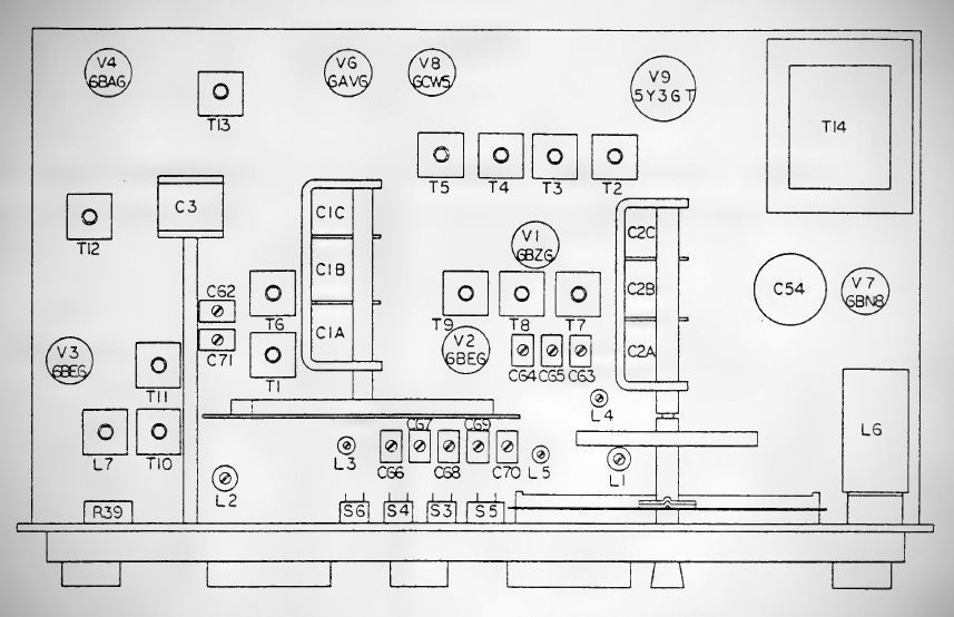
Tube Complement (8 Tubes)
Note: even though the tubes are numbered V-1 – V-9, there is no V-5.
– 6BZ6 (RF Stage)
– 12BE6 (1st Mixer/HF Oscillator)
– 12BE6 (2nd Conversion Mixer/2nd Oscillator)
– 12BA6 ($230\text{ KC}$ IF Amp/Q-Multiplier)
– 12AV6 (Detector/Audio Amp)
– 6BN8 (ANL/BFO)
– 6CW5 (Audio Output)
– 5Y3GT Rectifier
Power Requirements: 105–125 VAC, 50– 60 Hz, 75 watts.
Relationship to the NC-190
The NC-140 and NC-190 look like identical twins because, mechanically and structurally, they almost are. National introduced the NC-190 in 1961, and when they designed the lower-cost NC-140 in 1962, they directly reused the NC-190’s chassis, dial mechanisms, and "Cosmic Blue" cabinet.
However, if you look under the hood or try to align them, the electrical differences become very clear.
1. Selectivity Control (Potentiometer vs. Rotary Switch)
NC-190: Features a discrete 3-position rotary switch for selectivity, providing fixed bandpass widths of 0.6 kHz, 3.0 kHz, and 5.0 kHz.
NC-140: Uses a continuously variable potentiometer on the front panel. It controls feedback on a single regenerative IF stage (acting like a Q-multiplier), giving you infinitely adjustable selectivity from 0.5 kHz to 5.0 kHz.
2. IF Stage Complexity
NC-190: A more robust design featuring two dedicated IF amplifier stages.
NC-140: A simplified, budget-conscious design that has only one IF amplifier stage. To make up for the loss of gain and to keep selectivity sharp, National made this single stage highly regenerative.
3. Tube Layout & The Parts Bin Swap
Both radios utilize a somewhat odd mix of 6 and 12 volt tubes. National originally bought these 12 volt tubes in massive quantities for their incredibly popular NCX-3 transceiver. To save money, they designed the NC-140 to use them, requiring a unique power transformer with multiple filament windings.
Because the NC-140 sold poorly and was ultimately cancelled, National ended up with a large surplus of NC-140 power transformers. To burn through the inventory, late-production NC-190s were built using the NC-140's chassis and power transformers, leading to a lot of confusion for restorers when their NC-190 doesn't match the early 6V-only schematics.
⚠️ Alignment caution: If you are servicing an NC-140, do not use the NC-190 manual for the IF alignment. Because the NC-140 relies on a regenerative IF stage for its selectivity, the process for setting up the intermediate frequency feedback loop is entirely different from the NC-190's standard bandpass alignment.