Note
QST, Oct 1958, inside back cover.
CQ, Oct 1958, inside back cover.
QST, Nov 1958, inside back cover.
QST, Dec 1958, inside back cover.
Allied Radio catalog 1959 (issued in 1958), p. 375. (list of converters)
QST, Jan 1961, inside back cover.
QST, Apr 1962, inside back cover.
Allied Radio catalog 1963 (copyright 1962), p. 284.
Allied Radio catalog 1964 (copyright 1963), p. 221.
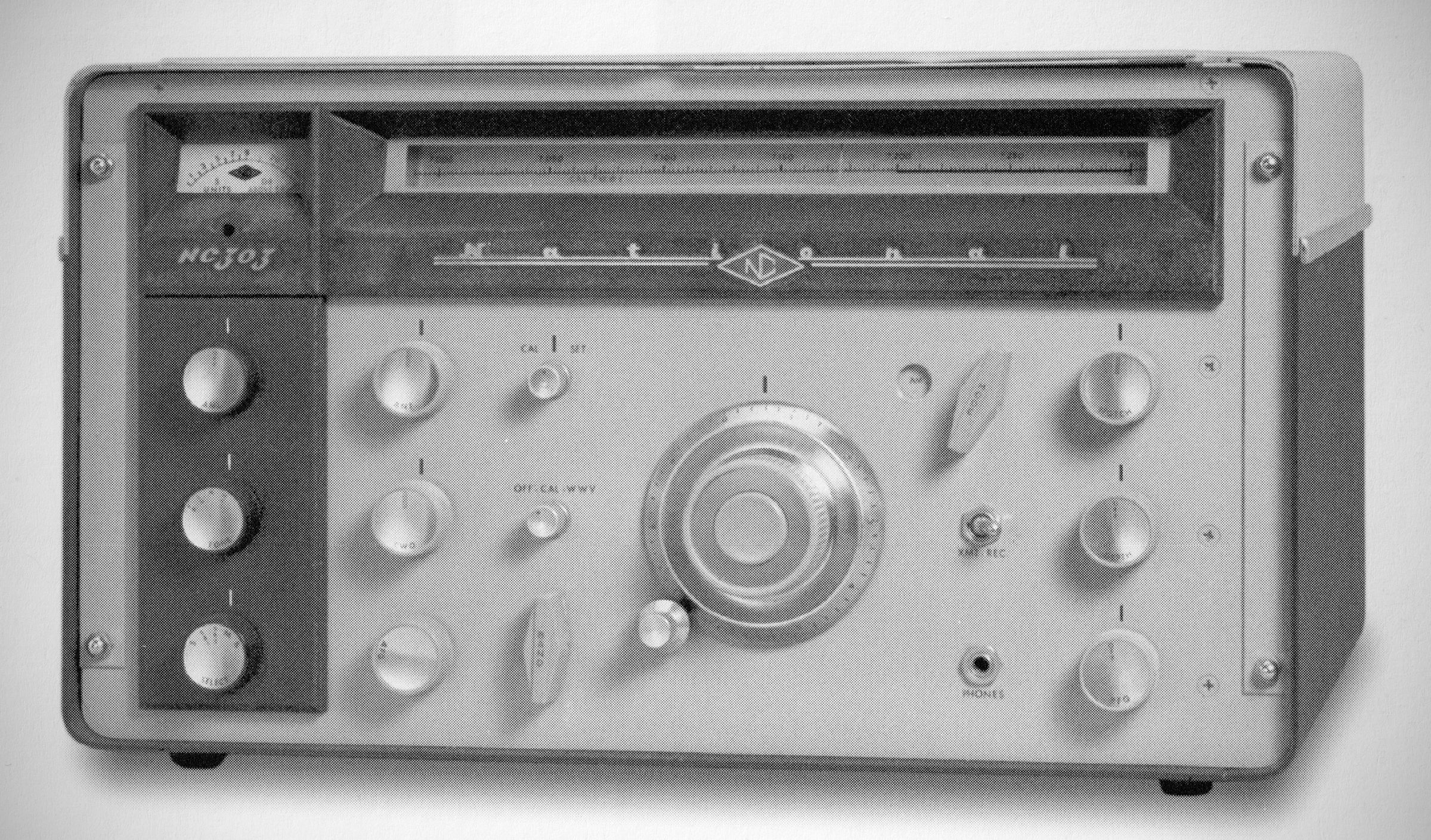
The NC-303 added new features to the NC-300 and changed others. It eliminated the 2215 kHz IF crystal filter and added a Q-multiplier in the 80kHz IF. A separate SSB/CW noise limiter was added, and the AVC circuit improved. It covered the 160–10 meter ham bands and included a 5 MHz wide tuning range to use with optional 6, 2, and 1-1/4 meter converters. Calibrated tuning scales for the VHF bands were included.
Features an integrated slide-rule dial drum that mechanically rotates with the band switch, displaying only the dial scale corresponding to the active tuning range.
Incorporates a weighted main tuning knob coupled to a backlash-free gear train with a 40:1 ratio, alongside a push-to-engage rim-drive vernier that provides an additional 7:1 tuning reduction.
The receiver directly tunes seven primary amateur bands and includes a 30 to 35 MHz tunable intermediate frequency band (designated as the "X" band) for use with external crystal-controlled converters:
160 Meters: 1.8 to 2.0 MHz
80 Meters: 3.5 to 4.0 MHz
40 Meters: 7.0 to 7.3 MHz
20 Meters: 14.0 to 14.4 MHz
15 Meters: 21.0 to 21.5 MHz
11 Meters: 26.5 to 27.5 MHz
10 Meters: 28.0 to 29.7 MHz
"X" Band: 30.0 to 35.0 MHz
Dial Type: Rotating slide-rule drum linked to the band switch. The dial drum also includes dedicated direct-reading scales for 6 meters (49.5–54.5 MHz), 2 meters (143.5–148.5 MHz), and 220.0–225.0 MHz when paired with the matching National NC-300 series broadband converters.
– Architecture: A 15-tube double-conversion superheterodyne receiver.
– Intermediate Frequencies: First IF is centered at 2215 kHz; second IF operates at 80 kHz.
– Voltage & Current Regulation: Incorporates an 0B2 gas-discharge tube for B+ voltage regulation on the oscillators and a 4H4-C current stabilizer tube to regulate the first conversion oscillator's filament current.
– Variable Selectivity: A five-position selectivity control offers selectable IF bandwidths:
S (super sharp) 400 Hz centered at 80 kHz for CW reception.
SB1 & SB2: 2 kHz bandwidths centered at 81.5 kHz and 78.5 kHz, permitting single-knob upper or lower sideband selection for SSB and AM.
M (Medium): 3.5 kHz bandwidth centered at 80 kHz for standard AM phone.
B (Broad): 8 kHz bandwidth centered at 80 kHz for net operation or high-fidelity VHF reception.
– Q Multiplier: Features a tunable rejection notch operating in the second IF passband with variable depth control to eliminate interfering heterodyne tones.
– Dual Noise Limiters: Contains two separate noise-limiting circuits—an automatic threshold-setting limiter for AM reception and a manually adjustable, double-ended limiter for clipping positive and negative noise spikes on SSB and CW signals.
– AGC & Metering: Features a fast-attack, slow-release AGC system tailored for SSB operation, paired with an illuminated S-meter calibrated from S-1 to S-9 and up to +40 dB over S-9.
– Audio Shaping: A four-position TONE control (HI, N, LO, PK) allows customization of audio response, including a peak (PK) setting that narrows bandpass response for CW copy.
– Audio Output Power: 1 watt at 10% total harmonic distortion.
– Output Impedance: Screw terminals configured for a 3.2 ohm to 4 ohms. External speaker (or 500-ohm line matching depending on transformer taps).
– Antenna Input: High-impedance / random wire connection via rear binding terminals (nominal 50 to 70 ohms when using matching connectors).
– Muting & Break-In Connections: Includes built-in grid-block muting terminals capable of silencing the receiver when driven by a negative 22V to 50V source from a transmitter, alongside standby and antenna relay control connections.
– Calibrator & Accessories: Equipped with chassis sockets for an optional XCU-303 or XCU-300 100 kHz crystal calibrator unit (controllable via panel switch) and an accessory socket supplying heater and plate power alongside IF audio outputs.
The chassis and panel can be removed from the cabinet and rack-mounted using standard hardware.
Tube Complement (15 total):
– 6BZ6 RF Amplifier
– 6BA7 First Mixer
– 6AH6 First High-Frequency Oscillator
– 6BE6 Second Converter
– (2) 6BJ6First & Second IF Amplifiers
– 6AL5 AM Detector, Noise Limiter, and AGC
– 6AL5 CW/SSB Noise Limiter
6BF6 Heterodyne/Product Detector
– 12AX7 Q Multiplier
– 12AT7 S-Meter / Audio Frequency Amplifier:
– 6AQ5 Audio Output Amplifier
– 5Y3GT High Voltage Rectifier:
– 0B2 Voltage Regulator:
– 4H4-C Current Stabilizer:
– 1N1692 solid-state diode AGC Clamp Diode:
Power Requirements: 105–130 VAC, 50/60 Hz, 70 watts.
References
Brief description. Radio News, Dec 1958, p. 108.
Brief description. Popular Electronics, Dec 1958, p. 139.