Note
QST, Aug 1964, p.107. (Announced. Will be shown at Wescon in LA)
QST, Sep 1964, inside back cover. (Available)
QST, Jan 1965, p. 127.
Allied Radio catalog 1966 (copyright 1965), p. 357.
QST, Aug 1965, inside back cover. (Mark II)
QST, Nov 1965, p. inside back cover. (mentions accessories)
CQ, Mar 1967, back cover. (Not referred to as the Mark II, it is called the "New 1967 NCX-5."
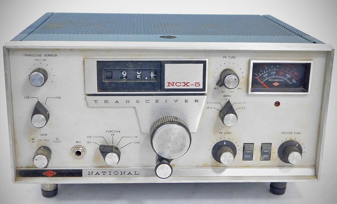
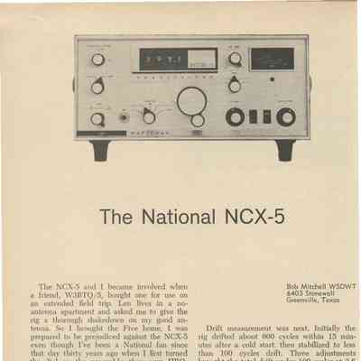
The NCX-5's solid-state, capacitor-tuned VFO was linked to a mechanical digital readout, enabling the frequency to be read down to 100 Hz. A vernier control provided receiver offset tuning of +-5 kHz. The NCX-5 used 15 semiconductors and 20 tubes. Power input to the 6GJ5 finals was 200 watts SSB/CW and 100 watts AM on 80 through 10 meters.
A defining feature of the NCX-5 is its solid-state VFO, which provides virtually drift-free performance right from turn-on, with stability rated at no more than 100 Hz of drift in any ten-minute window.
Instead of a traditional analog dial glass, frequency display is handled by a mechanical digital counter readout. The counter is accurate to 1 kHz across all bands, with additional sub-calibration down to 100 Hz. Tuning is uniform across all bands at a rate of 10 kHz per full 360-degree rotation of the main tuning knob.
Selectivity is provided by an 8-pole crystal lattice filter featuring a 2.8 kHz bandwidth at the 6 dB points and a steep 1.7:1 shape factor measured from 6 to 60 dB. The receiver section includes two RF stages, a product detector for SSB/CW, a separate dedicated AM detector, and fast-attack/slow-decay AGC.
The unit supports selectable upper or lower sideband (SSB), AM, and CW operation.
The final amplifier stage uses a pair of parallel 6GJ5 tubes working into a pi-network matching circuit capable of handling output loads between 40 and 60 ohms.
Other features include break-in grid-block CW keying with an internal sidetone oscillator, and front-panel selection between VOX, push-to-talk (PTT), or manual transmit switching.
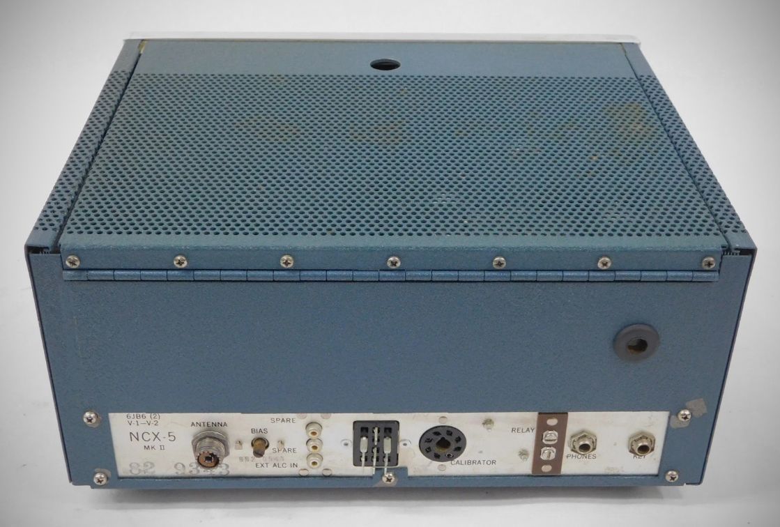
The only change in the NCX-5 Mark II was an entirely redesigned balanced modulator.
Specifications
– Frequency Range: With crystals supplied 3,500 to 4,000 kHz., 7,000 to 7,300 kHz., 14,000 to 14,500 kHz., 21,000 to 21,500 kHz., 28,500 to 29,000 kHz. (Three additional crystals required if coverage of entire 28,000-30,000 kHz. band is desired).
– Modes: SSB, AM, CW.
– Output Impedance Range: 40-60 ohms, Pi network.
– Frequency Determination: Double conversion with crystal-controlled high frequency oscillators and tunable second oscillator.
– IF: 6.02 MHz
– Dial Accuracy: One kilocycle over entire 500 kHz. tuning range on all bands.
– Dial Calibration: 100 cycles on all bands.
– Tuning Ratio: Identical on all bands; 10 kHz. per 360° rotation of main tuning control.
– Frequency Stability: Not more than 100 cycles variation in any ten-minute period from turn-on including variation in input voltage of ±10%.
– Suppression: Carrier -50 db, unwanted sideband 50 db, 3rd order distortion products -30 db at full output.
– Receiver Sensitivity: 0.5 uv for 10 db S/N in SSB mode.
– Audio Output: Better than 2 watts; 3.2 ohms.
– Microphone Input: High Impedance.
Tube and Semi-Conductor Complement: 20 tubes, 15 semi-conductors, 41 functions. Parallel 6GJ5's in P.A.
Tube Lineup (20 total)
– 6JB6 Final power amplifier
– 6JB6 Final power amplifier
– 12BE6 1st transmit mixer
– 6KE8 local oscillator, 2nd transmit mixer.
– 6GK6 RF driver stage
– 12AT7 speech amplifier, S-meter amplifier
– 12AU7 Carrier oscillator
– 6GH8 Microphone preamplifier, transmit-receive relay control
– 12AU7 1st and 2nd VOX audio signal amplifiers
– 6BA6 Transmit IF amplifier
– 6BZ6 RF amplifier
– 12BA6 2nd receiver RF amplifier
– 12BE6 1st receive mixer
– 12BE6 2nd receive mixer, converting signals down to the main
– 12BA6 1st IF amplifier, low-level amplifier in transmit mode
– 12BA6 2nd IF amplifier
– 12BA6 3rd IF amplifier
– 12AX7 Product detector, 1st audio amplifier
– 6AQ5 Audio power output
– 0A2 Voltage regulator
– 15 semiconductors
Operation requires an external power source, such as the matching NCX-A AC power supply or the NCX-D 12V DC mobile supply.
Power Requirements: 700 V.D.C. @ 300 Ma., 280 V.D.C. @ 160 Ma., -80 V.D.C. @ 10 Ma., 12.6 V. @ 5 A.
References
Review. 73, Oct 1965, p. 84.
See National's notes: QST, Aug 1964, p. 107.
See National's notes: QST, Sep 1964, p. 105.
See National's notes: QST, Mar 1965 p. 99.
See National's notes: QST, Aug 1965 p. 99.
See National's notes: QST, Feb 1966 p. 103.
See National's notes: QST, Apr 1966 p. 107.
Longer tube life. 73, Oct 1974, p. 119.