Note
http://www.antiqueradios.org/gazette/SWevol.htm
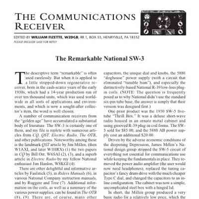
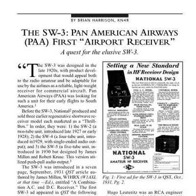
QST Oct 1931, p. 2.
Radio News, Jun 1932, p. 1062.
QST, Oct 1932, p. 68.
Lafayette catalog number 55, p. 68.
Radio News, Jul 1933, p. 51.
QST, Sep 1933, p. 59 (available with 2.5 volt AC tubes, 6 volt AC/DC, and 2
volt dry cell tubes)
QST Oct 1933, p. 74. "New and Improved"
Radio News, Jan 1934. p. 437.
Radio News, Jun 1934, p. 762. (now available in AC, DC, and 2 volt battery versions)
QST, Oct 1937, p. 55. (A few notes)
Lafayette catalog number 78, p. 146.
QST, Feb 1941, p. 59. (First major change)
QST, Jan 1965, p. 10. (a reference to SW3 in 1931)
Sometimes appeared in catalogs with model numbers like these:
ACSW-3, AC operation
6DCSW-3, 6 volt DC
2DCSW-3, 2 volt DC
National designed the SW-3 for the Great Depression market. Its circuit was similar to that of the SW-5, but lacked that model's push-pull audio output stage. It was eliminated in an effort to keep the selling price low enough to attract customers when it was introduced in 1931.
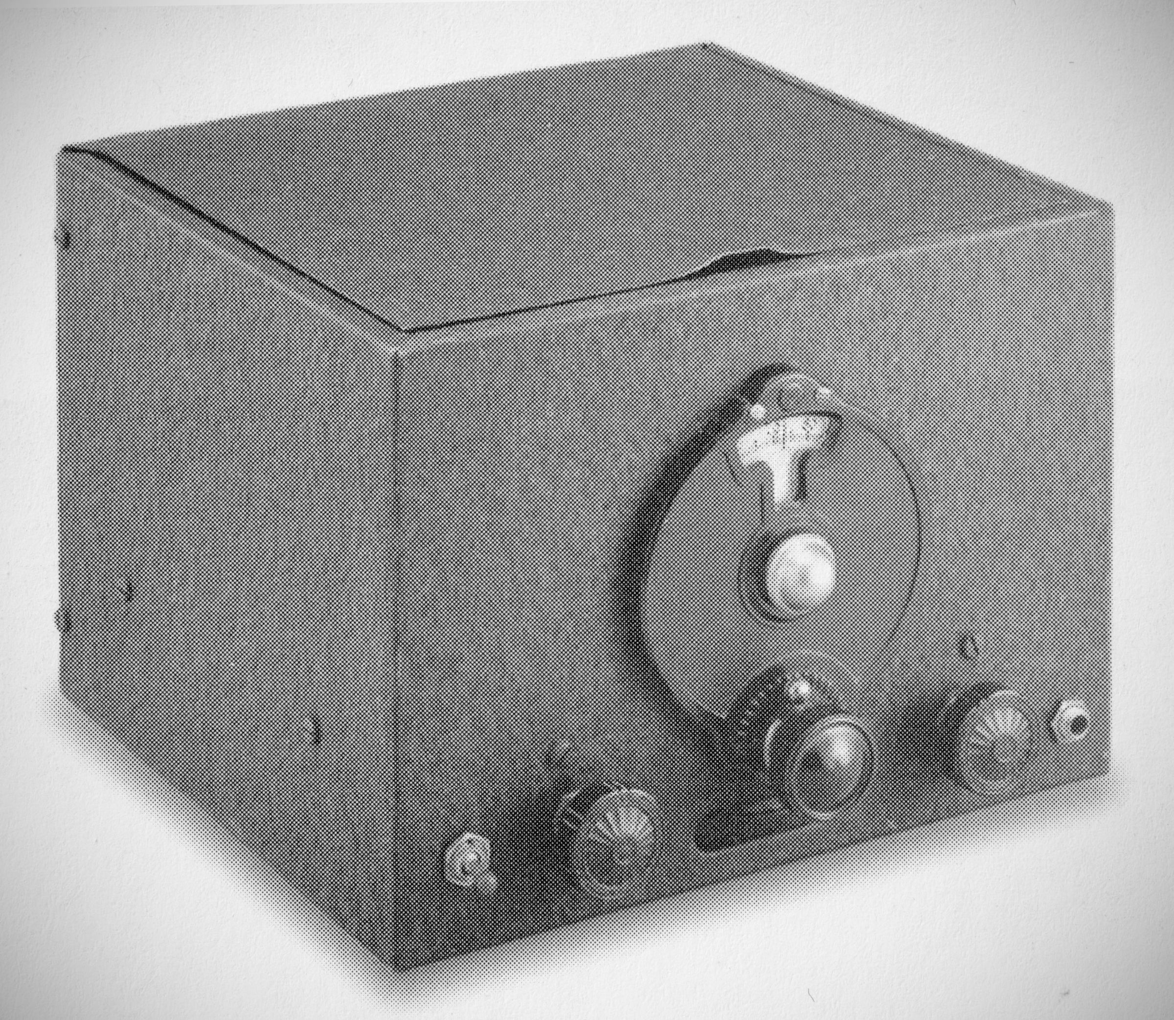
Introduced in the summer of 1931 by the SW-3 was a pioneering "all-wave" bandspread receiver designed exclusively for radio amateurs. It revolutionized receiver development and amateur radio. Over 10,000 units were manufactured during a 14-year production run. It was widely used by amateurs, commercial stations, airlines, ships, and expeditions.
The receiver was designed in the late 1920s to appeal to radio amateurs and to serve as a reliable, lightweight receiver for commercial aircraft (specifically for Pan American's early flights to South America). It replaced the heavier and erratic SW-4 model.
Because National did not initially hold an RCA license, the very first units were sold unwired to limit patent infringement liability. They were presumably wired by a dummy company called "Jackson Laboratories" (named after a street where National was located) before being shipped.
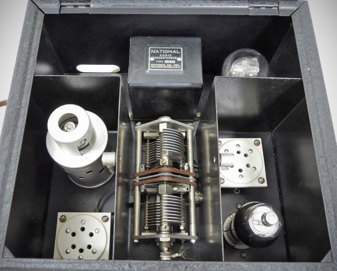
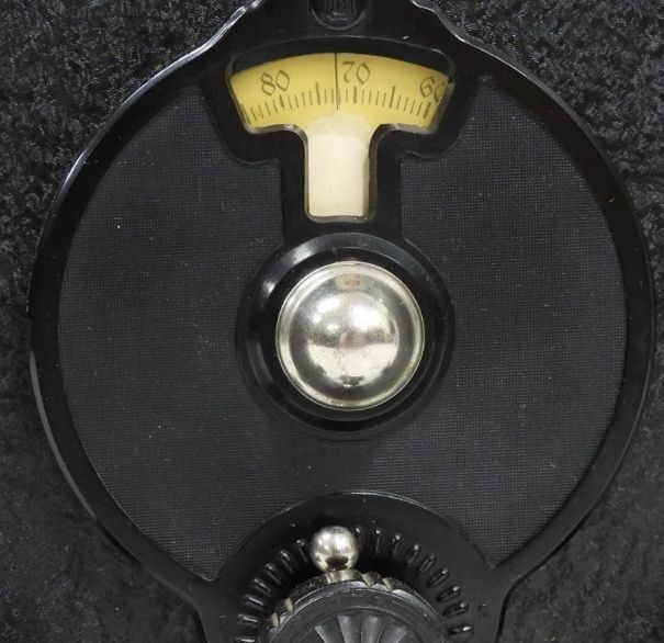
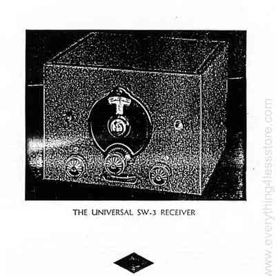
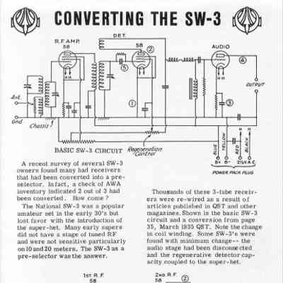
The SW-3 is a simple, 3-tube set consisting of a tuned RF stage, a regenerative detector, and a single audio amplifier. It features a "single dial control" with ganged RF and detector tuning. The front panel includes a horizontal RF gain thumb dial (below the main tuning dial), a left-hand RF tuning control, and a right-hand regeneration control.
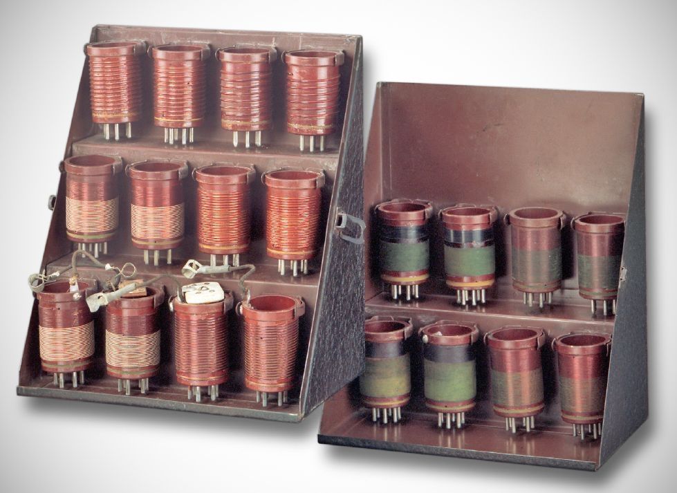
The receiver utilizes a unique set of plug-in coils made from a precision, high-Q molded mica-filled bakelite material trademarked as "R-39". These coils kept moisture out, ensuring uniform inductor performance regardless of the weather.
Key Features & Design Elements
– Tube Versatility: The AC version utilizes the Type 35 variable-mu tube as a highly stable regenerative grid detector, which smooths out regeneration control. The battery/D.C. version employs 6-volt heater-type tubes (Types '36 and '37) that drastically reduce the microphonic noises common in older battery-operated sets.
– Flexible Power Options: Operators can run the receiver completely on AC, completely on batteries, or via a favored hybrid method using DC for the tube heaters and "B" batteries for the plate supply. This hybrid setup offers exceptional stability and eliminates the regeneration-control "detuning effect" on weak signals.
– Advanced Shielding: To prevent the RF stage from oscillating and interlocking with the detector, the receiver uses a precisely spaced steel chassis welded to the cabinet. Steel was chosen over aluminum to protect the unit from low-frequency (60 Hz) hum.
– Single-Control Ganged Tuning: True single-dial tuning is achieved by mounting two 90 µµf capacitors in tandem. They are linked by an isolated, flexible insulating coupling to break the common shaft, which eliminates interlocking tendencies.
– Low-Loss R-39 Coil Forms: The RF transformers are wound on a specialized, moisture-resistant molding material called R-39. This material eliminates the dielectric losses associated with standard Bakelite, resulting in noticeably higher sensitivity and selectivity.
– Calibrated Attenuation Control: Built underneath the chassis to prevent feedback, a 500 kΩ tapered potentiometer serves a dual purpose as a volume control and an approximate audibility meter mapped to the "R" signal intensity rating system.
Models and Variations
Three basic models were produced over the receiver's lifespan, utilizing different tube configurations:
– Model One: The initial version used 2.5-volt glass tubes (two 35s and a 27) and color-coded "10-20" series coils. Two other versions of Model One were briefly made: a 6-volt variant (using 36 and 37 tubes) for mobile use, and a 1.4-volt d.c. battery-operated variant (using 30 and 32 tubes).
– Model Two: The most popular and common version, appearing around 1936. It used interchangeable 2.5-volt or 6.3-volt pentode tubes (58 or 6D6 tubes for the RF and detector stages, and a 27 or 76 triode for the audio amplifier) alongside "60" series coils.
– Model Three ("Universal"): Released near World War II, this model featured metal tubes (6J7 and 6C5) and a switching system that allowed conversion to 1.4-volt octal battery tubes (1N5 and 1A5). It utilized "30-40" series coils.
Performance and Operation
The SW-3 covered the radio spectrum from 9 to 2000 meters 33.3 MHz to 150 kHz) using 10 coil sets, with additional specialized coils providing bandspread for the 10, 20, 40, 80, and 160-meter amateur bands.
Despite being designed in 1931, the SW-3 was highly sensitive on lower bands (160, 80, and 40 meters) and handles CW and SSB signals impressively well with very low background noise. However, it is prone to overloading on strong local modern signals, which operators usually fix by adding a small variable capacitor in series with the antenna.
Power Requirements
It requires an external power supply or dry batteries via a 4-prong plug, operating on a plate supply of 125 to 200 volts at a total current drain of less than 20 milliamperes.
Chart of coil numbers versus frequency and model:
Range Model 3 Model 2 Model 1
--- --- --- ---
90-160 kHz 42 72 22
150-220 kHz 41 71 21
190-280 kHz 40 70 20
250-390 kHz 39 69 19
320-650 kHz 38 68 18
500-900 kHz 37 67 17
690-1500 kHz 36 66 16
1500-2700 kHz 35 65 15
2500-4500 kHz 34 64 14
4200-8000 kHz 33 63 13
7.0-12.0 MHz 32 62 12
12.0-21.0 MHz 31 61 11
19.0-35.0 MHz 30 60 10
> Note: Bandspread coils have suffix letter A. For example, the 80 meter bandspread coils are 34A, 64A or 14A. Early Model 1 coils are not numbered, but are color coded.
The following coil data appeared in a National ad (source and year unknown) and is for the Model 2 type described above.
60 8 –14 meters
61 13 – 25 meters
62- 23 – 41 meters
63 40 – 70 meters
64 65 – 115 meters
65 115 – 200 meters
AMATEUR BAND SPREAD COILS
61A 20 meter band
63A 40 meter band
64A 80 meter band
65A 160 meter band
References
Technical description. QST, Sep 1931, p. 9
Convert to superhet. Radio, Apr 1934, p. 12.
Brief description. Radio News, Jun 1934, p. 762.
Convert to superhet. Radio, Mar 1936, p. 38.
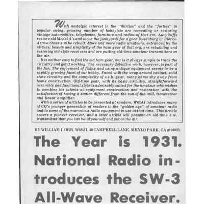
"National Radio Introduces the SW-3," CQ, Jul 1971, p. 34.