Note
Radio News, Jun 1929, p. 1147.
Radio News, Sep 1929, p. 273. (inside photo)
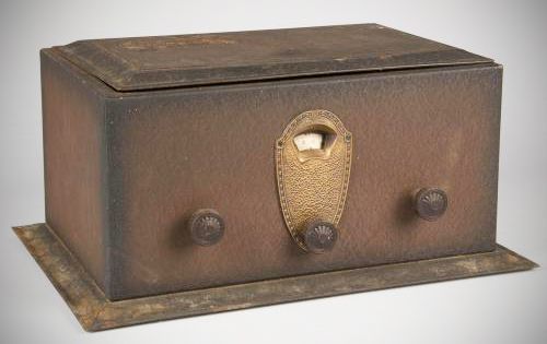
National replaced its original Thrill Box (unofficially called the SW-2) in June 1929 with a new version designated the SW-4 (also called a Thrill Box, and later designated SW-4, because it has four tubes). it was manufactured using custom-made tooling and included a cabinet. The fourth tube functioned as an audio power amplifier. Not actually referred to as the SW-4 until September 1929.
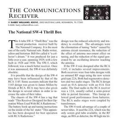
The National SW-4 "Thrill Box" was a 4-tube shortwave regenerative receiver produced by The National Company. Introduced around late 1928 and manufactured through 1929 into early 1930, it was National's second production receiver and stands as the rarest of their early sets.
The SW-4 utilized a 4-tube circuit design featuring an untuned RF stage, a regenerative detector, and two audio stages:
– RF Stage: Employed a type 22A (222) screen-grid tube in an untuned configuration, which eliminated antenna tuning "holes" and reduced oscillator radiation, though it sacrificed some selectivity.
– Detector Stage: Used a 00A (200A) gaseous detector tube, known for good conversion gain but high inherent noise (prompting many operators to swap it for an 01A).
– Audio Stages: Utilized a 40 (240) high-mu triode in the first audio stage and a 71 (171A) power triode for the final audio output.
Rather than using narrower-frequency transformers of the era, National implemented high-efficiency impedance coupling. The SW-4 was the first receiver to incorporate National's dual-section "Duo Coupler" units.
Type EC Dual-Section Tuning Capacitor: The tuning condenser featured a manual mechanical switch. Leaving the switch open isolated a rear 4-stator plate section for slow, precise shortwave tuning. Closing the switch placed the front stator plates in parallel, allowing fast tuning across the entire medium-wave AM broadcast band.
The SW-4 relied on interchangeable plug-in coils wound on 2-inch diameter phenolic forms. Four standard coils (A, B, C, and D) were included, while E and F coils could be purchased separately to extend the architecture into the broadcast band:
A 16,600 kHz – 10,700 kHz (18–28m) Switch Open
B 12,500 kHz – 7,500 kHz (24–40m) Switch Open
C 8,000 kHz – 4,600 kHz (37.5–65m) Switch Open
D 3,000 kHz – 2,650 kHz (60–115m) Switch Open
E 2,680 kHz – 1,750 kHz (110–175m) Switch Open
E 1,760 kHz – 1,000 kHz (170–300m) Switch Closed
F 1,034 kHz – 526 kHz (290–570m) Switch Closed
> Note on Materials: The coil forms were manufactured using wood flour and phenolic resin, making them somewhat hygroscopic; as a result, their tuning characteristics could subtly drift with changes in environmental humidity and temperature.
National sold the SW-4 as either a standalone parts kit or a factory-wired unit. Interestingly, completely assembled versions were shipped with an "Abbott Laboratories" sticker on the inside lid. Abbott Laboratories was a fictitious company named after the street running past the National factory—a clever legal subterfuge designed to bypass patent agreements with RCA that would have otherwise demanded a 10% royalty on all National revenue.
Tubes: (1) 222, (1) 200A, (1) 240, (1) 171A
Requires National's external "Velvet B" power supply.
+160 VDC
+135 VDC
+45 VDC
–45 VDC
and filament
References
Review. Radio News, Jun 1929, p. 1079.
Some Refinements. Radio News, Nov 1929, p. 443.