Note
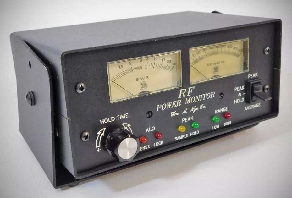
The Nye Viking RF Power Monitor (Models RFM-003 and RFM-005) is a station monitoring system that combines a fully automatic SWR meter, a peak and average reading wattmeter, a reverse power meter, and an integrated Amplifier Lockout (ALO) protection circuit.
The monitor utilizes two front-panel meters to track station performance simultaneously:
– SWR Meter (Left): Activated by very low RF power levels to provide direct, constant SWR readings that remain steady even as forward power increases.
– Power Meter (Right): Scaled 0–300 or 0–500 depending on the model, this meter measures forward or reverse RF power. It features an automatically switched multiplier that shifts between a High and Low range (indicated by front-panel LEDs), with one scale representing ten times the value of the other.
Power Measurement Modes
– Forward and reverse power can be evaluated using three user-selected modes:
– Average: Displays traditional average power levels.
– Peak: Measures actual peak power over longer sample times for modes like SSB, CW, AM, and Pulse, without storing the reading.
– Peak & Hold: Uses a specialized storage circuit to capture short-duration RF pulses ($\ge 1\text{ ms}$) and hold the maximum display for up to 20+ seconds, regulated by a front-panel adjust knob. Front-panel LEDs indicate whether the circuit is currently sampling or holding.
Amplifier Lockout (ALO) Feature
The ALO feature is a protective safety mechanism designed to safeguard external power amplifiers and their vacuum tubes from damage caused by unsafe antenna loads or severe mismatching.
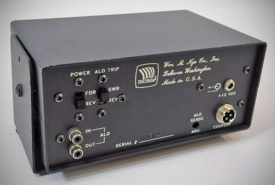
The internal ALO relay (rated for 5A at 120VAC / 28VDC with isolated contacts) must be wired in series with the amplifier’s relay control line using the rear-panel RCA phono jacks (`ALO IN`).
A rear-panel toggle switch allows operators to select between two trip parameters:
SWR Method: Trips when a specific SWR threshold is met. It is factory set to a 2:1 ratio but can be adjusted across a 1.6:1 to 7:1 range.
Reflected (Reverse) Power Method: Trips at a chosen reflected wattage. The adjustment range depends entirely on the directional coupler in use:
"K" Series Couplers: Adjustable from 40–400 watts (factory set at 100W).
"C" Series Couplers: Adjustable from 4–40 watts (factory set at 10W).
⚠️ Operational Note: An ALO lock will only trigger if the forward power meter is operating on its high scale. Once tripped, a front-panel "LOCK" LED illuminates, and the relay remains locked until roughly 5 seconds after RF drive is removed (extended by an extra 5 seconds if operating in Peak & Hold mode).
Directional Couplers
The RFM units rely on remote, completely interchangeable directional couplers connected to the display housing via a flexible control cable. The RF input and output utilize standard PL-259/UHF coaxial connectors inline with a 50-ohm transmission line.
The coupler circuitry relies on two primary internal toroids:
T1 (50 turns on a ferrite core): Senses transmission line voltage/current for forward and reverse power detection.
T2 (20 turns on a ferrite core): Captures RF to supply a +7.5 VDC output back to the monitor to power the circuitry and charge the internal NiCad batteries during operation.
Specifications
– Accuracy: ±5% of full scale.
– Sample Time (Peak & Hold): Typically 1 ms (3 ms maximum).
– Hold Time: adjustable from 0.5 to 20 seconds.
– Power Consumption: 64 mW typical operational, with a 450 mW maximum.
Power Source: Internal 4-cell AA rechargeable NiCad battery pack (B1). The batteries are automatically charged by applied RF when using HF couplers, or via an external 12V charger.