Note
QST, Dec 1981, p. 224.
QST, Jun 1982, p. 181.
Converts from 10 to 500 kHz.
VLF-A converts to 3510–4000 kHz
VLF-B converts to 4010–4500 kHz
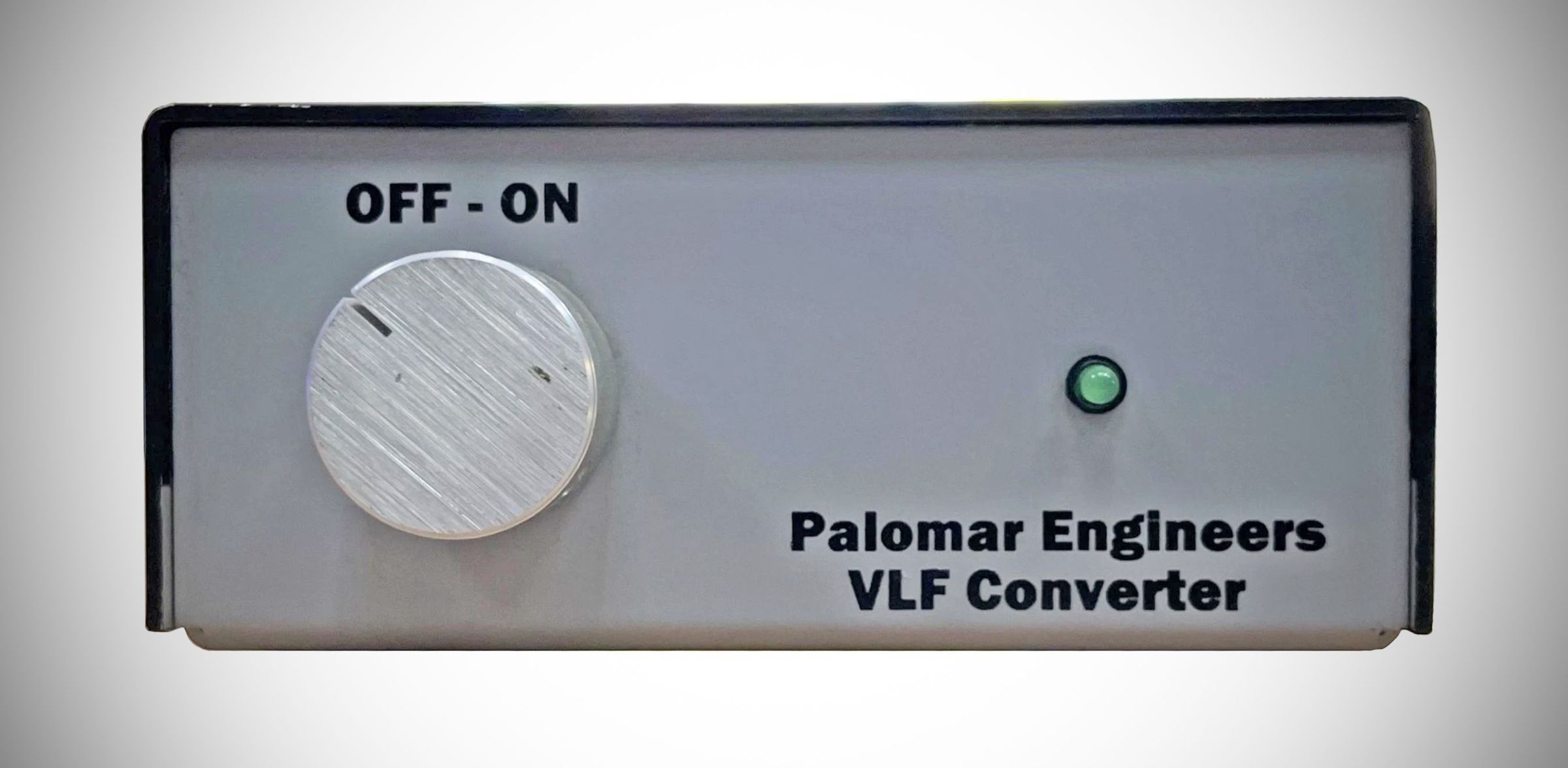
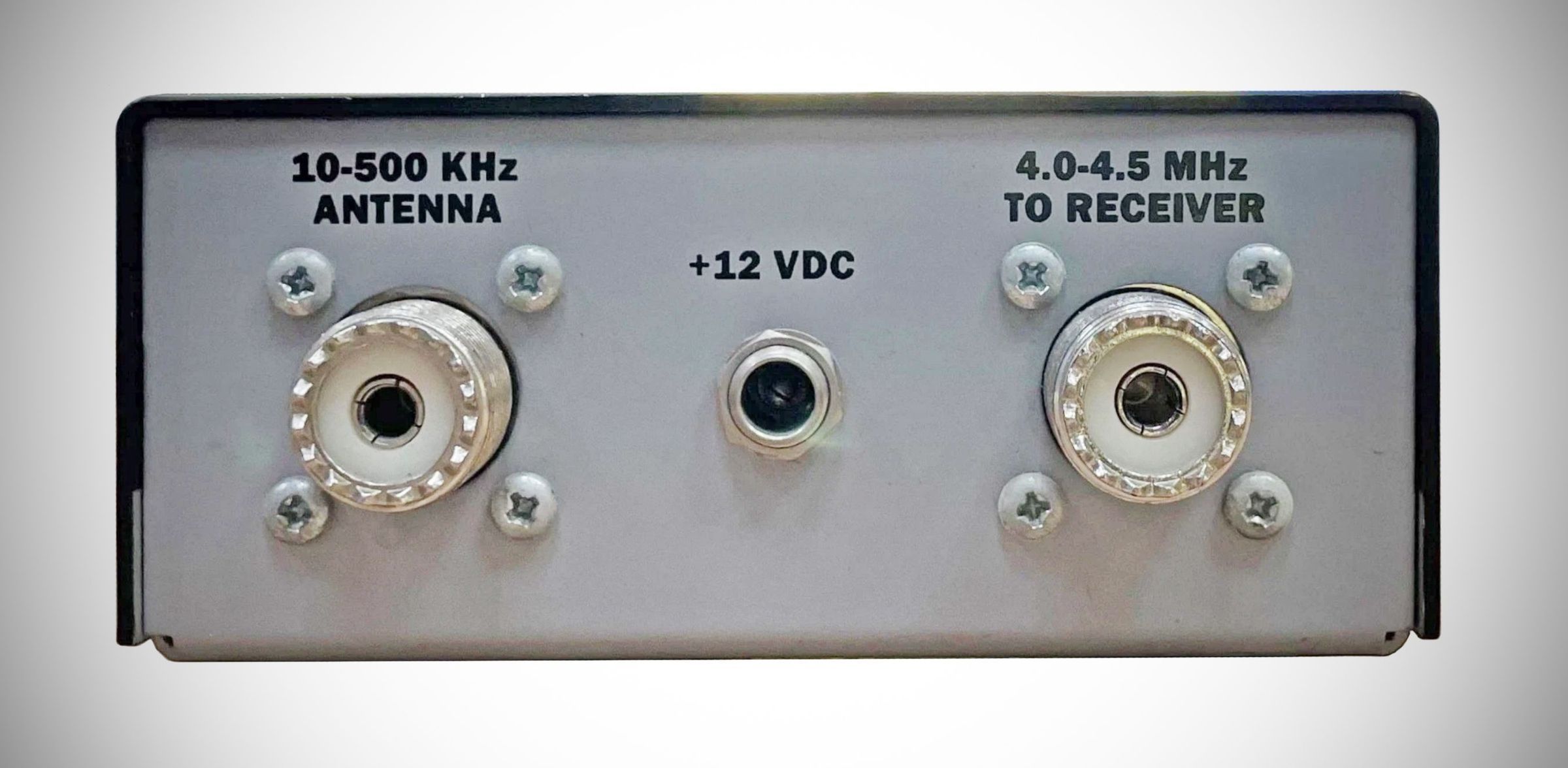
There isn’t much to the Palomar VLF converter and that is one of its strong points. This little 2 × 4.25 × 4.25-inch unit is designed for the easiest installation possible. You connect your antenna to the SO-239 input, then attach a coaxial jumper between the converter output connector (another SO-239) and your radio. There is one switch on the front panel labeled ON and OFF, along with a green LED to indicate the ON state. The converter needs an Input of 12VDC.
The Palomar converter is simple on the inside as well. Incoming signals are first subjected to a 3-stage low-pass filter, which is essential to block overload from nearby AM broadcasters. After the low-pass filter the VLF signals reach a mixer stage composed of a 1496 mixer IC and a crystal-controlled oscillator designed around an MPF102 transistor.
ARRL Lab Measurements: Palomar VLF-B Converter
Current consumption: <20 mA
L.O. Accuracy: 6.9 kHz error
Conversion gain: 0 dB to –14 dB (loss), frequency dependent
Conversion gain over frequency:
Frequency (kHz) Gain (dB)
10 –7
20 –5
50 –4
100 –2
150 0
200 –2
250 –5
300 –9
400 –12
500 –14