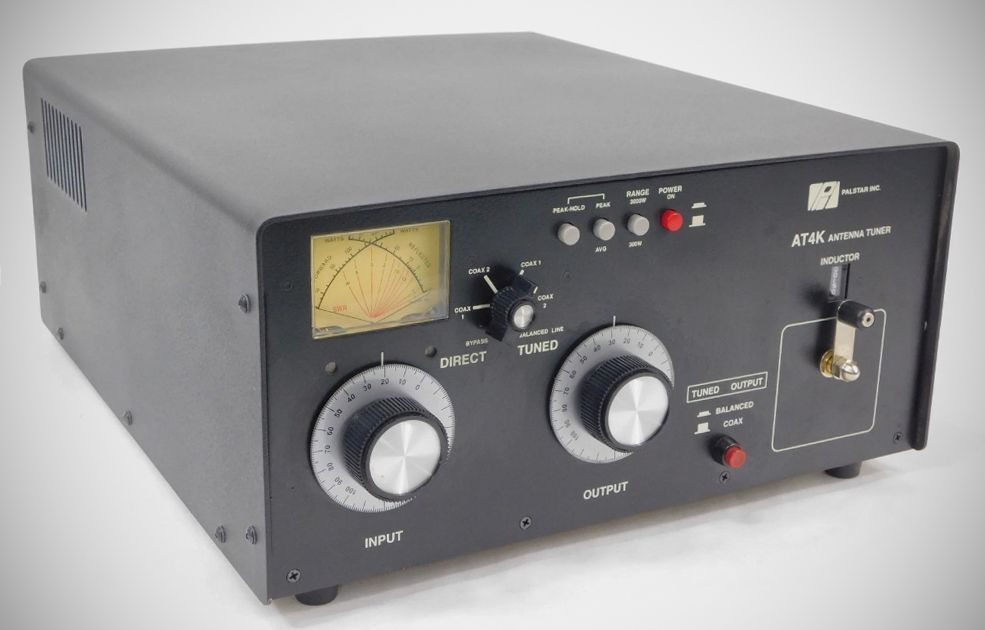
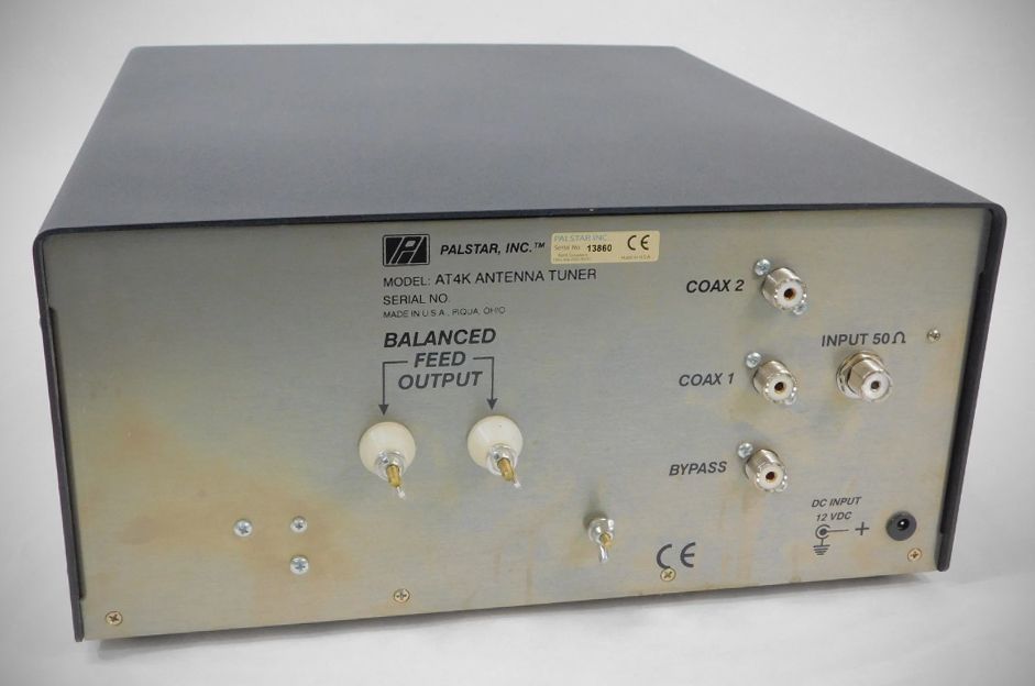
The 2011 version of the AT4K made a few changes. These included a built-in version of the PM2000A watt meter, which provided an active peak and peak hold circuit. This requires external 12V DC power to operate the active components that "capture" the peak of an SSB signal and hold the needle for 1–2 seconds.
Also, the manual jumper on the back was replaced by a front-panel relay switch, allowing you to toggle between balanced and unbalanced outputs without reaching behind the rig.
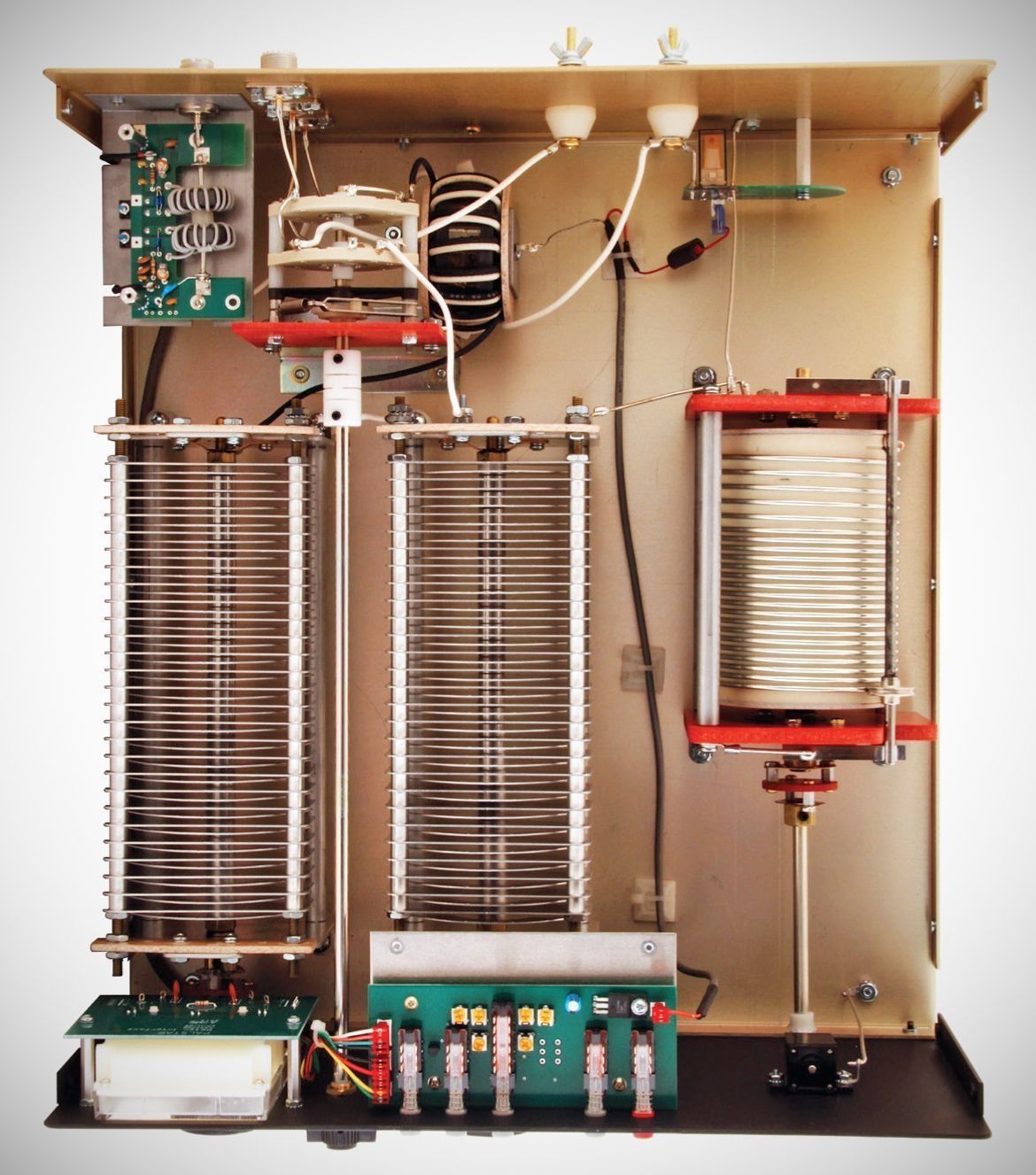
Finally, the capacitors were upgraded to 460 pF (or 500 pF) at 6 kV, and the inductor was refined to a silver-plated ceramic body design to prevent self-resonance issues on 15 meters that occasionally cropped up in the very first runs.
The AT4K is notable for its design, which places the 1:1 balun at the input rather than the output—a technical detail that presents a 50 ohm impedance at the input and output of the balun--for high power handling capability.
Features
– Maximum Power: It supports 2500 watts single tone continuous and 3000 watts PEP.
– Frequency Range: The unit covers 1.8 MHz to 29.5 MHz
– Impedance Range: It handles a wide range from 8 Ω to 2000 Ω, assuming a resistive load.
– Circuitry: It utilizes a T-matching network with a 1:1 current-type ferrite balun located at the input.
– Cross-Needle Meter: A frequency-compensated dual-movement meter displays Forward power, Reflected power, and SWR simultaneously.
– The metering circuit supports True Active Peak and Peak Hold (2-second duration). Essentially a built-in Palstar PM2000A.
– Power Scales: A two-position switch selects between 300 W and 3000 W ranges.
- Antenna Selection: A 6-position switch allows users to choose between Coax 1 (tuned or bypass), Coax 2 (tuned or bypass), Bypass, and Balanced output.
Specifications
– Frequency Coverage: 1.8 to 29.5 MHz.
– Power Maximum: 2500 W single tone continuous, 3000 W PEP.
– Impedance Range: 8 to 2000 Ohms, 160m to 10m (assuming resistive load).
– Balanced Output: 1:1 current type balun at input using Ferrite.
Power requirements: 12 VDC (200-500 ma) for the meter lamp, peak circuits, and relay.
Power Specifications by Impedance
The manual provides specific maximum power ratings based on the antenna impedance (assuming single tone key down):
Antenna Impedance Max Power Rating
8 Ohms – 15 Ohms 500 watts (all bands)
15 Ohms – 25 Ohms 1000 watts (all bands)
25 Ohms – 50 Ohms 1500 watts (all bands)
50 Ohms – 2000 Ohms
160m: 2000 watts;
80m-15m: 2500 watts;
10m: 1000 watts