Note
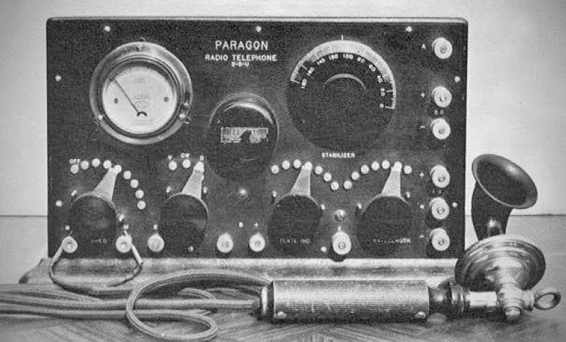
The Paragon 2-5-U was produced during an era when manufacturers began testing the market with complete, commercially built transmitters encased in fine cabinets with professional panel layouts, contrasting the "Ham-built" breadboard layouts common at the time.
The circuitry is highly similar to the early 1DH circuit. Notably, it completely lacks a tank condenser in its original configuration. Instead, the transmitter relied on the antenna itself as the prime oscillating circuit, where the antenna's capacitance combined with coil L to dictate the wavelength.
The front panel features an RF meter, a "Mode" switch to change between CW, AM, and ICW, and various binding posts. Due to component supply scrambles in the 1920s, the physical build of the panel varied over its production run:
– RF Meter Variations: Units were sold through different outlets with three different types of 0-1 Amp meters: early models used Eldredge hot-wire meters; later models used General Radio 127-A hot-wire meters; and versions sold through Montgomery-Ward utilized Jewell Pattern 640 thermo-couple RF meters.
– Binding Post Variations (Early Models): Featured six standard-sized posts on the right margin labeled top-to-bottom: A (Antenna), B+, B-, A+, A-, and E (Ground). Along the bottom were six smaller posts arranged in pairs for M (Microphone), K (Key), and B (Buzzer Battery).
– Binding Post Variations (Later Models): Featured six standard posts on the right labeled A (Antenna), BB, and ABN, while the E (Ground) post was moved to the bottom between the Plate and Wavelength switches. The bottom row was reduced to five smaller posts labeled M-K (Common), M (Microphone), K (Key), and B (Buzzer Battery).
Lifting the cover reveals the following internal setup:
– Tubes: It features sockets designed to accommodate two 5-watt tubes (specifically, UV-202 tubes in the original design).
– Filament Rheostat: Composed of wire coils soldered directly to the contacts of the left-hand tap switch.
– Coil & Tuning: Features a coil (designated as coil L) wired to two tap switches (1 for Wavelength and 2 for Plate Inductance). Coil L has a tap range of 6.5 to 70 microhenries.
– Stabilizer: A variometer sits at the top of the coil form, providing an inductance range of 160 to 540 microhenries.
– Condenser: Centered behind a Century High Frequency Buzzer is a Dubilier or Wireless Specialty .01 mfd, 1000V plate supply bypass condenser.
– Power & Modes: Rated as a 10-watt transmitter capable of handling AM, CW, and ICW (interrupted continuous wave) modes.
– Operating Range: The large values of the coil and variometer permitted operation from 160 to 352 meters (1875 to 923 kHz). It was rated to work with any antenna possessing a capacity between .00025 and .002 MF, a resistance up to 50 ohms, and a plate voltage from 80 to 500 volts.
Performance Quirks: Because it relied on the antenna as the oscillating circuit, it suffered from severe frequency instability (antenna swaying in the wind or changes in ground moisture would shift the frequency). All panel adjustments interlocked, buzzer ICW and AM modulation created wide sidebands, and CW keying produced distinct "chirping".
Historical Range Claims: According to its original catalog, the transmitter successfully achieved voice communication over a distance of 15 miles during the day (using one UV-202 tube and a 100-volt B battery) and reached over 500 miles at night on CW (using two UV-202 tubes with 350 volts).