Note
Radio News, Jul 1946, p. 85. ("new, improved")
QST, Aug 1946, p. 147.
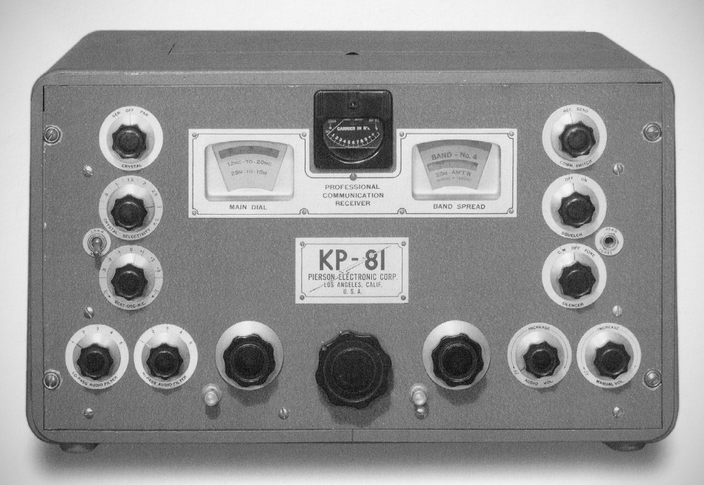
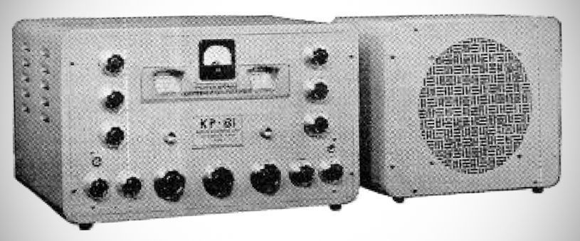
Receiver designer Karl Pierson worked for Patterson Electric before the war and also partnered in his own company, Pierson-Delane. His first post-war effort was the KP-81 receiver, a 20-tube, single-conversion set that tuned from 0.54-40 MHz in five bands. It used a moving-coil rack for band switching and had both a crystal filter and cascaded transformers for IF selectivity. The KP-81 's power supply was housed in its speaker cabinet.
The KP-81 it is exceptionally rare and represents a high-water mark of post-WWII radio design, characterized by outstanding selectivity, sensitivity, and stability.
The KP-81 is physically split into two separate, ruggedly constructed units built of heavy-gauge, ribbed steel:
1. The Receiver Unit: House the tuning mechanism, RF and IF stages, and all operator-adjustable controls.
2. The Power Supply & Speaker Unit: Houses the power transformer, filter circuits, push-pull audio output stage, and a heavy-duty 10-inch dynamic loudspeaker (available in either electro-dynamic or permanent magnet configurations).
Basic Features
16 Tuned IF Circuits & Twin Transformers: Operating at an intermediate frequency of 465 kc., the IF section utilizes series-connected twin transformers to achieve a sharp, nominal 4 kc. bandpass.
Crystal Filter: A precision, single-peak crystal filter with isolantite insulation, air-dielectric phasing, and separate shielding. It supports both series operation (selectivity adjustable from 500 Hz to 3 kc. for adjacent-station CW isolation) and parallel operation (providing a sharp notch to attenuate single-frequency heterodynes).
Automatic Noise Silencer: A sophisticated, automatic IF noise-canceling circuit utilizing three dedicated tubes (threshold control, noise amplification, and noise rectification). It features dedicated "C.W." and "Fone" modes.
500 kHz Crystal Calibration Oscillator: A built-in, crystal-controlled marker generator. Rotating the bandspread dial fully counter-clockwise to the "XTAL CAL ON" position activates a micro-switch that grounds the antenna input and turns on the oscillator, providing accurate marker signals every 500 kHz across the spectrum.
Squelch Circuit: Fully adjustable "silent-between-station" squelch that works down to and below the local noise level on any band.
High & Low Pass Audio Filters: Features independent 5-position high-pass and low-pass audio filters in the input of the first audio stage. This provides 25 distinct combinations of audio selectivity, ranging from an extended fidelity mode for music to a razor-sharp 600 Hz peak for CW reception.
Communication-Normal Switch: When placed in the "Communication" position, it automatically rolls off all audio frequencies above 1500 Hz to combat ionospheric hiss and improve voice intelligibility.
Audio Output Stage: Features a push-pull Class AB1 amplifier utilizing two 7C5 tubes to deliver 12 watts of undistorted audio to the built-in 10-inch speaker, alongside a 500-ohm rear terminal output for external speakers. A front-panel headphone jack (2,000-ohm impedance, 18 milliwatts max output) automatically silences the speaker when in use.
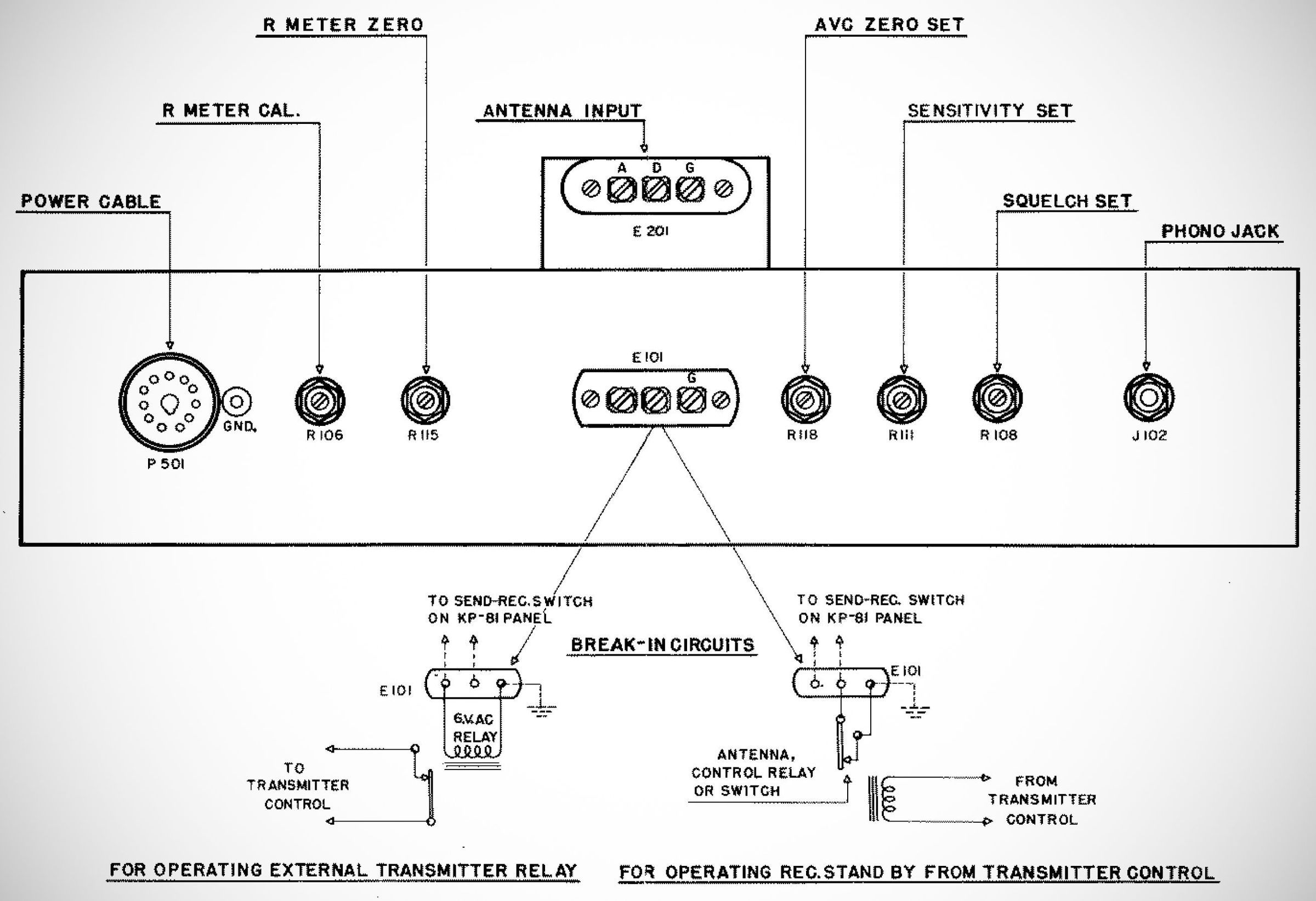
Phono Input Jack: High-impedance auxiliary jack on the rear panel that routes external signals directly through the receiver’s volume control and audio filters while automatically disabling the RF stages.
Balanced Bridge "R" Meter: Measures signal strength for both CW and phone signals. It reads $R1$ at 1 microvolt input, with each $R$ unit up to $R9$ representing a 6 dB change (and broader logarithmic scaling beyond $R9$).
Climatic Sealing: All close-tolerance coils, inductors, capacitors, resistors, and audio components are climatically sealed for long-term reliability.
Antenna Protection: Shunted by two neon lamps (1/10 watt) to protect the sensitive input circuitry from high-power RF burnouts, detuning the antenna stage if voltage spikes occur.
Specifications
– Frequency Coverage: 540 kc. to 40 MHz) across five bands
– Slide Coil Drawer (Catacomb): To change bands, the receiver utilizes a heavy-duty, cast-aluminum sliding coil drawer. This design physically moves the selected coil assembly directly beneath the main tuning condensers, utilizing silvered knife-switch contacts to engage spring-actuated arms. This layout ensures the shortest possible RF leads and completely isolates unused coils.
– Image Rejection: Thanks to two continuously operating, high-efficiency tuned RF pre-selector stages, the receiver achieves excellent image rejection ratios:
Over 7,000 to 1 on Band 1
Over 1,000 to 1 on Band 5
– Sensitivity: 0.5 microvolts for 1 watt of audio output
– Stability: Highly stable local oscillator design; plate voltage variations of up to 50% have a negligible impact on frequency, even at the highest bands.
Tube Lineup: 20 (mostly loctal) tubes total
"R" Meter V.T.V.M: 7A7
Squelch Circuit: 7C7
First Audio Amplifier: 7B4
500 KC Crystal Cal. Oscillator: 7C7
First R-F Amplifier: 7A7
Second R-F Amplifier: 7A7
Modulator (Mixer): 7B8
H-F Oscillator: 7B5
First I-F Amplifier: 7A7
Second I-F Amplifier: 6L7
Noise Rectifier: 7A6
Noise Amplifier: 7H7
Noise Control: 7A7
Third I-F Amplifier: 7B7
Detector: 7A4
Beat Frequency Oscillator: 7C7
AVC-Detector Rectifier: 7Y4
Power Supply Rectifier: 5U4G
Audio Output Amplifier: 7C5
Audio Output Amplifier: 7C5
Power Requirements: Designed for 115V AC (50–60 Hz) operation, with internal jumper configurations to support 230V AC.
References
Brief description. Radio News, May 1946, p. 148.