Note
QST, Aug 1960, p. 117.
QST, Oct 1961 p. 149. (62B)
QST, Feb 1963, p. 119
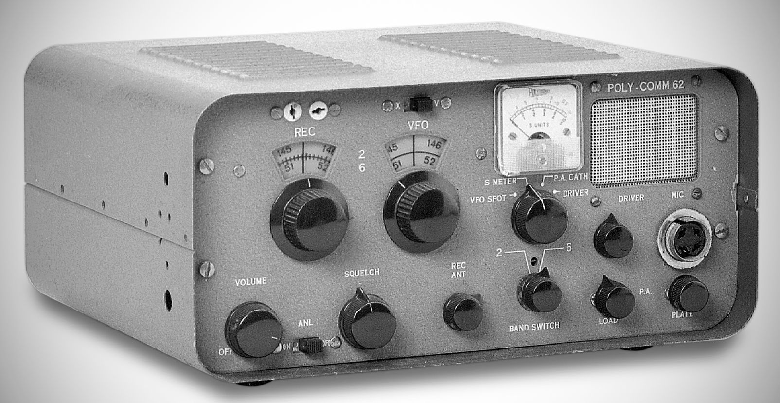
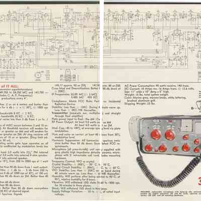
The Poly-Comm 62B is a compact dual-band transceiver. It covers both the 6-meter and 2-meter bands with a self-contained VFO and a universal power supply.
The built-in universal power supply allows operation from either an AC line or 12.6V DC for mobile setups using a conventional vibrator circuit. Power sources are switched simply by plugging in the appropriate power cord. Silicon diodes in a voltage doubler supply the high voltage.
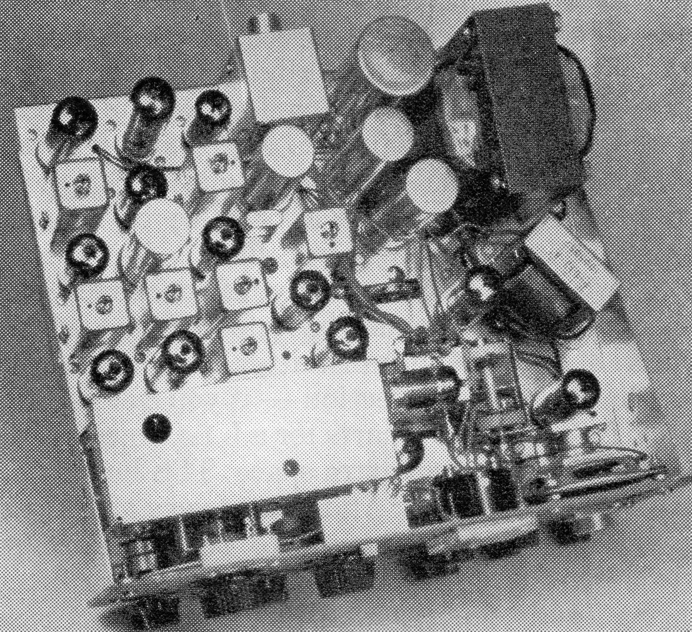
The receiver tuned circuits and transmitter VFO are shock-mounted for vibration and shock resistance.
Uses separate SO-239 connectors for 6 and 2 meters, though an internal strap allows the use of a single dual-band antenna connector if preferred.
Designed for AM reception only. It utilizes a 12-tube superheterodyne layout featuring triple conversion on 2 meters and double conversion on 6 meters.
The 62B uses a high-gain, cathode-coupled dual-triode RF stage feeding a Nuvistor first mixer. The second mixer uses a gang-tuned Colpitts VFO (46.595 MHz) yielding a second IF of 5.405 MHz. The third mixer uses a 4.95 MHz crystal oscillator to derive the final 455 kHz IF frequency, which passes through two stages of amplification.
Bench testing measured a 6 dB bandwidth of 3.9 kHz and a 40 dB bandwidth of 19.5 kHz. Sensitivity is excellent, bringing weak signals up out of the noise.
Audio & Squelch: Uses silicon diodes for detector, AGC delay, and ANL functions. A dual triode drives parallel-connected 6BQ5 audio output tubes, which double as modulator tubes in transmit mode. Includes an internal 2.5-inch speaker, rear external speaker terminals, and a fully adjustable squelch circuit.
Power Output: Bench tests measured power output (into a 50-ohm load) at 9 watts on 54 MHz and 5.5 watts on 148 MHz.
Performance Notes & Drawbacks
VFO Thermal Drift: The transceiver's main weak point is transmitter VFO drift. From a cold start at 144.312 MHz, the VFO drifted down 106.0 kHz in the first 30 minutes, 24.0 kHz in the second 30 minutes, 12.0 kHz in the third, and 2.5 kHz in the fourth 30 minutes.
Receiver Drift & Retuning: Receiver drift on 2 meters measured an upward drift of 27 kHz over 35 minutes before settling and drifting down 12 kHz over the next hour and 37 minutes. Due to its narrow selectivity, retuning during warmup is required.
Front Panel Ergonomics: While the recessed front panel provides protection in mobile environments, the large microphone connector makes the power amplifier tuning and loading controls somewhat difficult to reach. Additionally, the overhang of the cabinet can slightly obscure the meter and dials when placed flat on a desk.
Features
– Covers 250 kHz either side of both bands for CAP use
– 18 watt power input
– S meter doubles as tune-up meter, actually samples RF for maximum output
– 100% plate modulation...
– VFO. or crystal control for transmit built-in
– Triple conversion on 2 meters, dual on 6 meters
– Delayed AGC
– All oscillators voltage regulated
– Squelch and ANL
– Sensitivity: better than 0.8 uV on 2 meters, better than 0.2 on 6 meters for 10 db S/N/N ratio
– Selectivity: (6 kHz @ 6 db point)
– All temperature compensated circuits and Hi-Q IF stages utilizing 12 tuned circuits
– Single knob bandswitching...
Power requirements
115 VAC / 12 VDC power supply
References
Review (62B): QST, Apr 1962, p. 50.
Review (62B): 73, Apr 1962, p. 12.