Note
CQ, Nov 1957, p. 157.
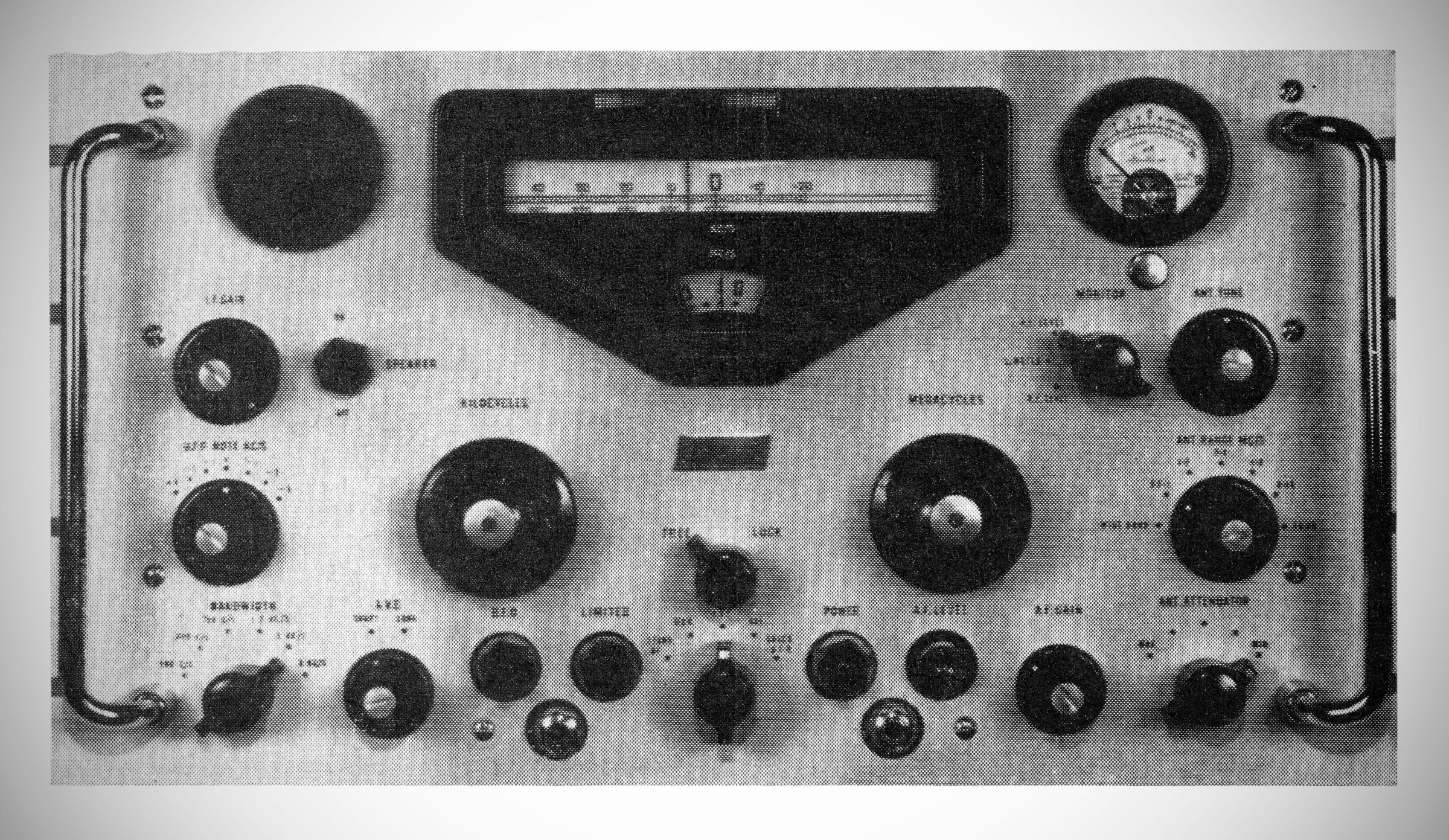
The Racal RA.17 is an HF communications receiver spanning the 500 kHz to 30 MHz range, built using a rugged, solid cast aluminum chassis and a ⅜-inch aluminum front panel designed to withstand demanding climates. First engineered in the 1950s, the receiver achieved widespread fame and became a staple for military forces, broadcasting authorities, and major communications networks worldwide, with over 15,000 units produced across its various production runs and derivatives.
The defining feature of the RA.17's design is its "Wadley Loop" drift-canceling frequency-changing circuit. This innovative architecture entirely eliminates the complex wiring and mechanical bandswitches typically found in conventional RF front ends, utilizing instead an electronic bandswitching system that locks tuning stability directly to a highly accurate 1 MHz internal crystal oscillator.
Mechanically and operationally, the receiver offers an expansive tuning experience, featuring an effective film scale dial length of approximately 145 feet. This allows for incredible resetting precision, providing a constant tuning rate where roughly 6 inches of scale length corresponds to 100 kHz.
The receiver incorporates a triple-conversion superheterodyne design: The wideband input signal is first mixed with a variable frequency oscillator (VFO1) to create a wideband first IF centered at 40 MHz. This is mixed again in a drift-canceling stage to generate a 2 to 3 MHz second IF, which is then tuned by a conventional superheterodyne interpolation receiver (VFO2). The final IF chain operates at 100 kHz, offering six switchable nominal bandwidths ranging from a wide 13 kHz down to a razor-sharp 100 Hz for CW and telegraphy.
Additional standard features include an onboard 100 kHz crystal calibrator, a versatile Beat Frequency Oscillator (±8 kHz range) for CW/SSB reception, manual or automatic gain control with switchable short/long time constants, and a series noise limiter.
Due to its immense popularity across different global regions, the receiver was produced in distinct geographical variants. The standard British model (such as the advanced RA.17L) utilizes typical European tube line-ups (such as the ECC189, EF91, and E180F). Conversely, the North American variant—designated as the RA.17C-12—was fully redesigned to meet American component standards. It utilizes unified thread screws, BNC/Type 83 coaxial connectors, a higher-power 1-watt audio output stage, silicon diode power rectifiers, and a standard North American tube compliment to simplify field maintenance and logistics.
Specifications
– Frequency Range: 1 to 30 MHz (range extends to 0.5 MHz with slight degradation of performance).
– Stability: After warm-up, drift in output frequency less than 50 Hz per hour under conditions of constant supply voltage and ambient temperature.
– Tuning: Effective scale length of approximately 145 feet, i.e., about 6 in. of scale length corresponds to 100 kHz. Frequency increments remain substantially constant over the entire band.
– Calibration: A 100 kHz signal derived from a 1 MHz crystal oscillator, having an accuracy of 5 parts in $10^7$, provides check points at 100 kHz intervals.
– Input Impedance: 75 ohms unbalanced.
Antenna Input:
(a) Wideband.
(b) Double-tuned in six bands:
(i) 0.5 to 1.0 MHz
(ii) 1 to 2 MHz
(iii) 2 to 4 MHz
(iv) 4 to 8 MHz
(v) 8 to 16 MHz
(vi) 16 to 30 MHz
– Sensitivity:
A1 reception (bandwidth 3 kHz): 1 µV for 18 dB signal/noise ratio.
A2 reception (30% modulated, bandwidth 3 kHz): 3 µV for 18 dB signal/noise ratio.
– Noise Factor: Less than 7 dB throughout the entire frequency range.
– Cross Modulation: For levels of wanted signal between 3 µV and 1 mV, an interfering signal 10 kHz off-tune and modulated 30%, must be at a level greater than 50 dB above that of the wanted signal to produce a cross modulation of 3%. The ratio of wanted to unwanted signal is improved at the rate of 3 dB/% up to 10% off-tune.
– Intermodulation: Better than 100 dB down for interfering signals at least 10% removed from the wanted signal.
– Blocking: With similar conditions to those for cross modulation, the unwanted signal level must be 60 dB above that of the wanted signal to reduce the audio output by 3 dB.
– Selectivity: Six alternative bandwidths are obtained by means of a selector switch. Filter details (nominal) are:
Setting -6 dB Bandwidth -66 dB Bandwidth
1. 13 kHz 35 kHz
2. 6.5 kHz 20 kHz
3. 3.0 kHz 15 kHz
4. 1.2 kHz 8 kHz
5. 0.30 kHz < 2 kHz
6. 0.10 kHz < 1.5 kHz
> Note on Selectivity: Bandwidths 5 and 6 are obtained with crystal-lattice filters; differences in centre frequencies of these bandwidth settings do not exceed 50 Hz.
– Image and Spurious Responses: With wideband or tuned input, external image signals are at least -80 dB, other spurious responses -60 dB. Internally generated spurious responses are not greater than 5 dB above receiver noise (3 kHz bandwidth and no antenna connected).
– B.F.O. Range: ±8 kHz.
– B.F.O. Stability: With constant ambient temperature and supply voltage, after warm-up time of 1 to 2 hours, drift does not exceed 50 Hz. For input level variations of 10 µV to 1 mV, b.f.o. drift is negligible.
– Automatic Gain Control (A.G.C.): A.G.C. is applied to the r.f. and the first 100 kHz i.f. stages only. An increase in signal level of 20 dB above 1 µV improves the signal/noise ratio by 18 dB. An increase in signal level of 100 dB above 1 µV increases the a.f. output by less than 7 dB.
– A.G.C. Time Constants:
Short: Charge: 25 milliseconds | Discharge: 200 milliseconds
Long: Charge: 200 milliseconds | Discharge: 1 second
– IF Output: 100 kHz at 75 ohms impedance. Level approximately 0.2V with a.g.c. in operation. Two outlets in parallel are provided.
– AF Response: With 13 kHz bandwidth, response remains within 4 dB from 250 Hz to 6000 Hz.
AF Output:
1. 50 mW from a switched 2 in. loudspeaker on the front panel (1 W, North American version).
2. Two headphone sockets in parallel on front panel.
3. Three independent outputs of 3 mW at 600 ohms at rear of chassis.
4. One output of 10 mW at 600 ohms. Pre-set level is independent of the a.f. gain control setting.
5. One output of 50 mW (1 W North American version) at 3 ohms.
> Note: Two headphone sockets are connected across the loudspeaker on the British version and across one of the 600 ohms, 3 mW outlets on the North American version of the receiver.
– Distortion: Not greater than 5% at 50 mW output.
– Hum Level: With A.F. GAIN control at maximum, the hum level is never less than 40 dB below rated output (50 mW or 1W respectively).
– Noise Limiter: A series noise limiter circuit can be switched into operation to provide limiting at modulation levels exceeding 30%.
– Meter Indication: Alternative switching for indication of signal carrier level or AF output level. Additional 'S' Meter indication on North American version.
External Connections:
Power Input
Aerial Input
2 to 3 MHz I.F. Input (for RA.137 L.F. Converter)
1 MHz Oscillator Output
100 kHz I.F. Output
VFO2 Output (for diversity coupling)
A.G.C. Line
A.F. Outputs
Tubes (American version): (1) 6ES8, (8) 6AU6, (1) 6AS6, (2) 6688 (2). (2) 6BE6, (4) 6BA6, (2) 6AL5, (1) 6AQ5, (1) 12AT7, (1) 5704.
Power Supply: 100-125 and 200-250 VAC, 45-65 Hz.
Power consumption: ~120 watt