Note
QST, Sep 1961 p. 102.
QST: Sep 1962, p. 107.
QST, Jan 1963, p. 135. (a division of Hallicrafters)
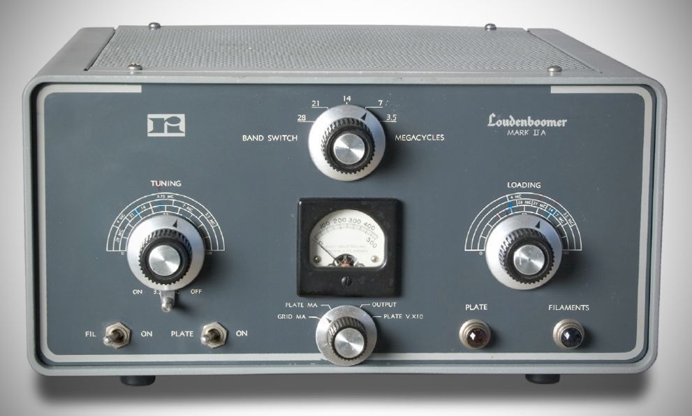
The Loudenboomer amp ran 2000 watts PEP using an Eimac 3-400Z triode. It worked on 80–10 meters and required an external power supply. The amp became the HT-45 after Hallicrafters acquired Radio Industries in 1963.
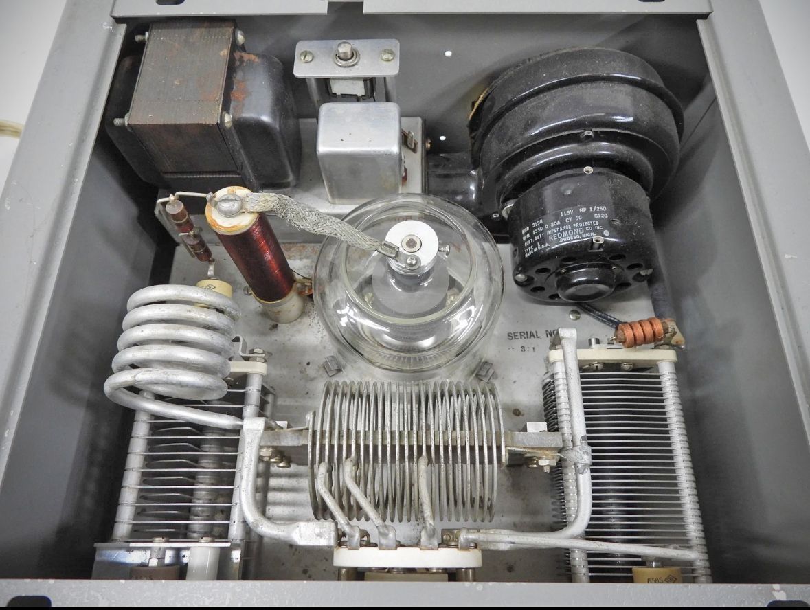
At the heart of the Loudenboomer Mark II is a single Eimac 3-400Z high-mu zero-bias triode featuring 400 watts of plate dissipation. Operating in a grounded-grid circuit, the design eliminates the need for grid or screen bias power supplies and requires no stage neutralization. The amplifier runs efficiently with just 45 watts of drive power to reach full input capacity.
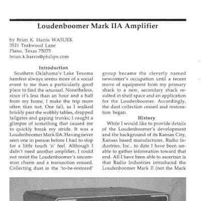
Housed in a two-tone gray enamel cabinet measuringThe front panel layout features a central meter capable of measuring grid current, plate current, plate voltage, and relative power output. Surrounding the meter are two large arched dial scales for main Tuning and Loading controls, a central Band selector knob, lower toggle switches for power and plate controls, and front-panel fuse holders.
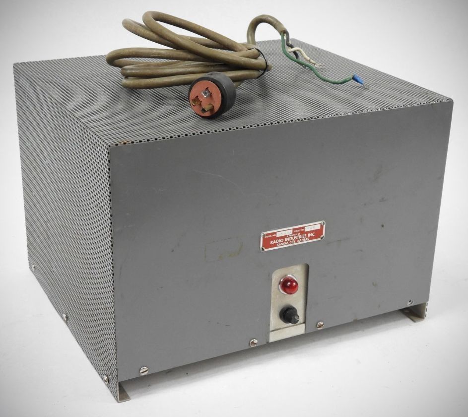
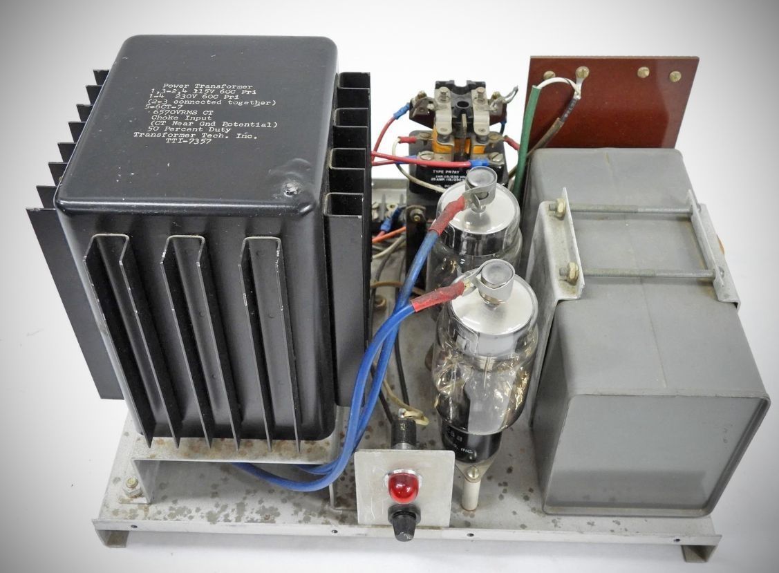
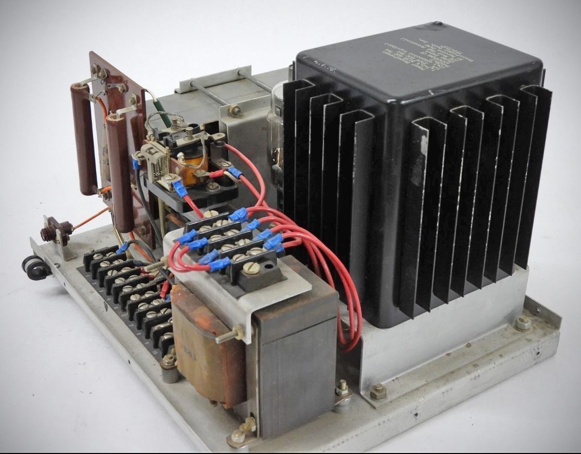
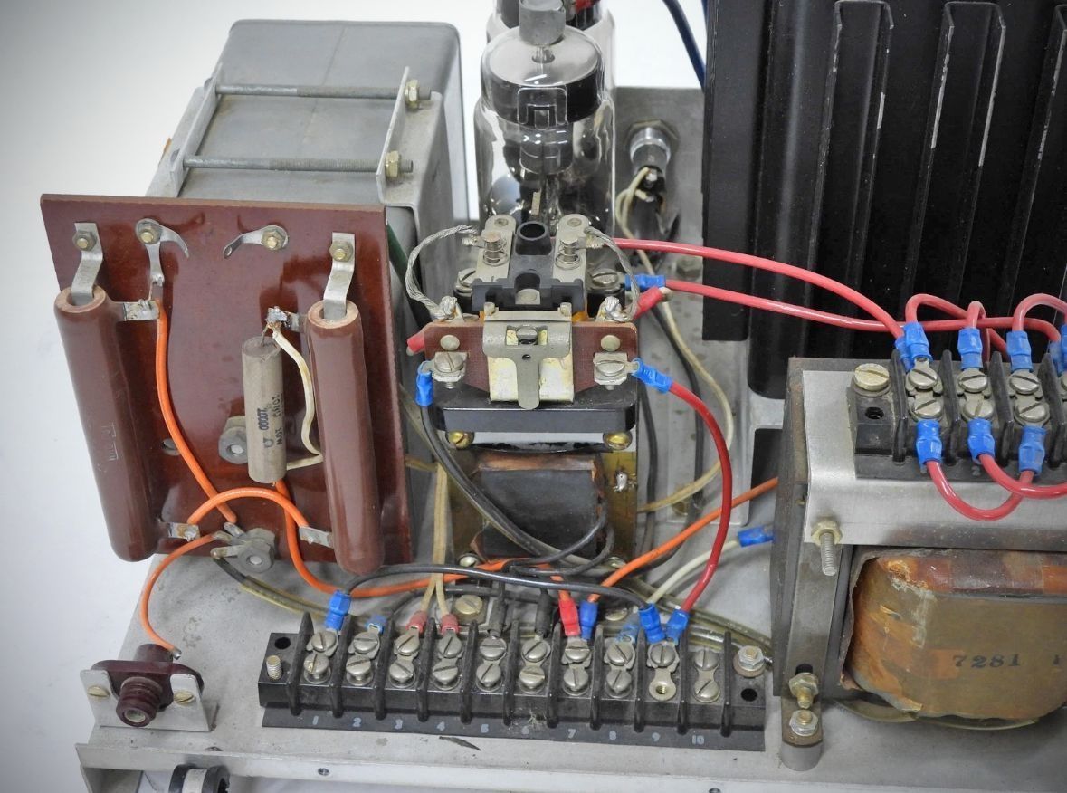
The amplifier requires an external high-voltage power supply capable of providing 2,500 to 3,000 VDC at 350 mA continuous. Radio Industries offered a matching 75 lb external power supply unit for $159.59, capable of operating from either 115 VAC or 230 VAC primary power lines.
– Frequency Coverage: The unit covers all amateur bands from 80 through 10 meters.
– Power Ratings: It is rated for full legal input power on SSB and CW, and up to 600 watts on AM.
– Low Drive Requirement: Requires only 45 watts of drive power to reach full input.
– Input and Output: Input impedance is rated at 50 ohms fed through a wide-band Ferramic transformer. The RF output utilizes an adjustable Pi-tank network nominally matched for a 50-ohm unbalanced load.
– Cooling and Power Controls: Forced-air cooling is provided by a 50 CFM blower. The internal filament transformer and blower operate on standard 115 VAC (60 Hz) power and are fused directly on the front panel. Panel circuitry is also included to remotely switch and control the external high-voltage power supply.
– Zero-Bias Tube Design: Utilizes a zero-bias Eimac 3-400Z triode with 400 watts of plate dissipation, eliminating the need for separate screen and grid power supplies.
– Remote Supply Control: Includes built-in panel circuitry for controlling the external high-voltage power supply directly from the Mark II front panel.
– Integrated Cooling and Filament Control: Features a 50 CFM cooling blower and a self-contained filament transformer operating on 115 VAC at 60 Hz, with both protected by front-panel fuses.
The Loudenboomer Mark IIA
By January 1963, Radio Industries was already a subsidiary of Hallicrafters. The last ad from Radio Industries appeared in May, and Hallicrafters announced the HT-45--their version of the Loudenboomer,–in December. The Loudenboomer Mark IIA was never advertised as such, so its isn't know wiith certanty when it hit the market
In an article appearing in the May 2003 issue of Electric Radio magazine, author Brian Harris, WA5UEK, mentions several differences in the MkIIA.
– Current-Limiting Resistor: The Mark IIA includes a 150-Ohm current-limiting resistor in the cathode return to reduce plate dissipation and idling current during standby, whereas the Mark II does not have this resistor.
– Grid Current Sensing: Grid current in the Mark II is sensed by measuring the voltage drop across a grid resistor, while in the Mark IIA it is sensed across a similar resistor in the cathode circuit.
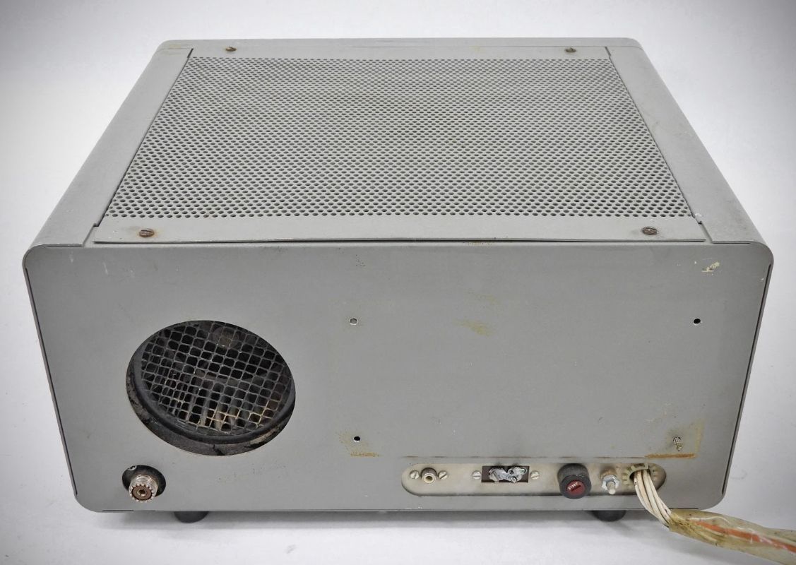
– Cabinet and Lid Design: The Mark II features a cabinet lid with a circle of perforations directly above the final tube, with sides that wrap down around the cabinet and secure with screws. †he Mark IIA features sides that wrap up and over, utilizing an almost fully perforated lid held in place with four 1/4-turn plastic fasteners.
Power Supply Differences
– Voltage Support: The Mark II power supply did not support 230V operation (the Mark IIA supply primary supports both 115V and 230V).
– High Voltage Indicator: The Mark II supply lacked the NE-51 neon high-voltage indicator lamp found in the Mark IIA supply.
– Plate Relay: The Mark II supply lacked the remotely controlled AC plate relay present in the Mark IIA supply.
References
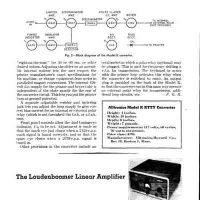
Review: QST, Jun 1962, p. 55.