Note
QST, Jan 1952, back cover.
QST, Feb 1952, p. 101. ($4.90)
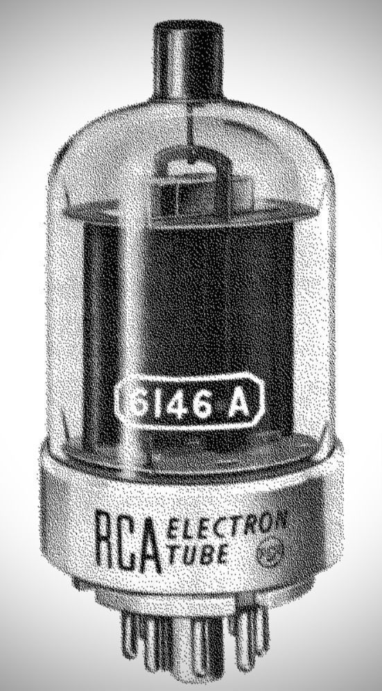
Few transmitting tubes have earned as legendary a status in the amateur radio and commercial communications world as the RCA 6146. Introduced by the Radio Corporation of America late in 1951 (first advertised in the January 1952 issue of QST), this compact, rugged, octal-based beam power pentode became the quintessential final amplifier for a generation of high-frequency transmitters.
Before the 6146, rigs often relied on larger glass or metal tubes like the 807, which, while capable, had long internal leads that limited their efficiency at higher frequencies. The 6146 changed the game by offering high power sensitivity, excellent efficiency up into the VHF range, and a remarkably compact footprint.
The history of the RCA 6146 beam power tube is one of the most storied chapters in mid-century communications engineering. Spanning from the early days of AM phone service to the highly demanding requirements of single-sideband (SSB) linear operation, the 6146 family became the absolute backbone of both amateur radio gear and commercial mobile FM communications.
However, beneath its ubiquitous success lies a fascinating corporate battle of technical one-upmanship between RCA and Sylvania, along with a messy engineering legacy regarding cross-compatibility that still traps vacuum tube equipment restorers today.
1951: The Genesis and the "Virtual Cathode Knee" Problem
The original 6146 was designed by the Radio Corporation of America (RCA) and made its public debut in 1951. At the time, Class C CW and AM phone were the dominant modes of radio service. For these modes, the original 6146 was an exceptional performer, offering 90 watts of CW input or 65 watts on AM phone.
Despite its success, the original 1951 RCA design suffered from a notable physical limitation known as the "virtual cathode knee" problem. Because it was a beam tetrode, space was deliberately left between the screen grid and the plate to allow an electron cloud—a virtual cathode—to form and act as a suppressor grid.
However, during heavy conduction cycles when the tube current surged toward 750mA and the plate voltage dropped to 150V, this virtual cathode cloud would become completely overwhelmed. This precipitated a sharp drop in plate current accompanied by a steep, almost vertical spike in screen grid current. While Class C amplifiers swamped this effect out cleanly, the emerging popularity of SSB and linear services in the late 1950s demanded strict linearity. Under Class AB1 linear service, this "knee" translated directly into severe signal distortion.
The Manufacturing Reality: Alignment and Matching
Compounding the linearity issue was a massive variation in plate current from tube to tube during production. Beam tetrodes naturally exhibited up to a 2:1 variation in plate current under identical grid voltages. For example, under specific test conditions, the plate current on an early 6146 could range anywhere from 45mA to 85mA.
This variance was caused by microscopic alignment tolerances during manufacturing. Grid Shadowing: For a beam tetrode to work efficiently, the screen grid (SG) must sit perfectly aligned in the physical shadow of the control grid (CG) when looking out from the cathode. If alignment slipped, the grid-to-plate capacity shifted, and control grid bias requirements varied wildly.
Because of this 2:1 spread, data sheets strictly mandated using matched pairs when running tubes in parallel (such as in the Hallicrafters HT-37 final amplifier). If unmatched tubes were paired, one tube would end up drawing significantly more current than its partner, unevenly sharing the load and engaging the radio's Automatic Level Control (AALC) prematurely, making the tubes appear weak or "soft".
1961–1963: Sylvania Strikes Back and "Controlled Zero Bias"
Recognizing the limitations of the RCA design in an SSB-dominated world, Sylvania blindsided the industry by releasing the 6146A in August 1961—a full 18 months before RCA could field their own version. Sylvania fundamentally re-engineered the tube to address its core weaknesses:
The Cathode Upgrade
Sylvania built their 6146A cathode using the ruggedized standards of their premium "Gold Brand" industrial lines. They swapped out pure tungsten filament wire for a Rhenium-Tungsten alloy, which was more ductile, less fragile under heat expansion, and significantly extended the lifespan of the heater. They also applied a dark coating over the filament's oxide insulator to maximize heat transfer to the cathode sleeve , and used a cold-rolled powdered metal sleeve to stop the emissive coating from peeling.
Fixing the Knee
Sylvania altered the physical spacing between the screen and the plate. By widening this gap, they stabilized the virtual cathode cloud. Now, the plate could be cleanly driven up to 900mA without the sudden current drop or resultant distortion that plagued the earlier type.
Controlled Zero Bias
Sylvania tightened manufacturing tolerances to guarantee a minimum benchmark of performance for Class AB1 linear service. This parameter, later termed "Controlled Zero Bias" when RCA partially copied the design in 1963, guaranteed that any tube off the line would deliver a minimum of .330A of plate current at zero volts on the control grid. This guaranteed that even the lowest-performing tube in a batch could cleanly reach its specified plate dissipation in SSB mode.
RCA rushed to respond, releasing an "improved" 6146 in January 1963 as a prototype, followed by their own version of the 6146A in May 1963, mimicking Sylvania’s dark cathode coating and parameters.
1964: The 6146B and the "Absurd Compatibility" Claim
In mid-1964, RCA introduced the 6146B (also cross-branded as the commercial 8298A). RCA launched a massive marketing campaign claiming the tube offered 33.3% higher power input (bumping CW/SSB ratings from 90W to 120W ICAS) and was unilaterally backward-compatible with older 6146 and 6146A sockets.
To achieve this higher rating, RCA did not actually upgrade the internal metallurgy of their plate to dissipate more heat ; instead, they simply raised the screen grid voltage parameters and increased the maximum allowable glass bulb temperature rating from 220°C to 260°C. Sylvania countered by releasing their own 6146B, but unlike RCA, Sylvania actually added a heavy copper laminate to the plate structure, which rapidly pulled heat away from internal hot spots and provided a genuine 25% safety margin in plate dissipation.
However, the claim of unconditional backward compatibility quickly proved to be a disaster in the field. The 6146B featured significantly different inter-electrode capacitances, distinct grid characteristics, and entirely different bias requirements compared to its predecessors.
The Neutralization Crisis
When amateurs dropped RCA 6146B tubes into precision gear like the Collins 32S series or the KWM-2, the existing fixed neutralization circuits could not handle the alternative capacitance. The tubes went into immediate parasitic oscillation, generating destructive RF currents that literally burned up the radios' neutralization components in short order. Collins was forced to officially retract their approval of the 6146B until the military—wishing to standardize on the ruggedized military 6146W version of the 6146B—forced a redesign of the neutralization circuits.
The Series-Filament Trap
An even more severe failure mode occurred in radios that wired the tube heaters in a series configuration (common in many mobile commercial FM rigs like the Motorola Motrac, as well as Heathkit SB-series transceivers).
To offset the resistance of their new Rhenium-Tungsten filaments, RCA had kept the same wire diameter as their original tungsten heaters. This design oversight reduced the 6146B’s heater current draw from the family standard of 1.25A down to 1.125A. Sylvania, by contrast, properly widened their 6146B filament wire diameter to maintain the exact, fully compatible 1.25A requirement.
When an RCA 6146B (1.125A) was mixed in series with an older 6146 or 6146A (1.25A), a destructive thermal runaway loop occurred:
1. Because the RCA 6146B drew less current, its internal resistance rose much faster as it heated up.
2. In a series circuit, this forced a disproportionate amount of voltage across the 6146B heater.
3. The circuit would stabilize with the older 6146 starved at just ~5.2V, while the RCA 6146B was severely overdriven at upwards of 7.1V.
4. The overheated RCA 6146B filament caused the screen grid to warp, melt, short out, and cause spectacular internal fireworks.
This compatibility flaw was so severe that Motorola faced a massive financial crisis in the late 1970s. After trying to simplify inventory by replacing older 12-volt 8032 tubes with the 12-volt "B" equivalent (the 8552), thousands of commercial Motrac mobile radios began violently self-oscillating. The tubes ran so incredibly hot that the glass envelopes were physically annealed during routine tune-up. When the radios encountered normal vehicular shipping vibrations, the weakened glass shattered completely, forcing Motorola to pay out massive warranty claims and rush order old-stock 8032 tubes to fix the mess.
Summary of the 6146 Lineage and Offshoots
By the twilight of the vacuum tube era, the 6146 family tree had branched into specialized industrial, heavy-duty, and alternative voltage variants:
The Baseline Family: The original 6146 (1951, 25W plate dissipation), the 6146A (1961/63, dark heater), and the 6146B (1964, 35W plate dissipation/different bias).
The Military 6146W: A ruggedized, shock-resistant version manufactured under strict military contracts. Because the military never labeled these as 'A' or 'B' variants, modern operators must read the printed date codes: any 6146W stamped before 1964 is an original 6146/A structure, while later dates match the volatile 6146B specifications.
The 12.6V / 26.5V Relatives: To accommodate heavy integration into automotive and aviation electrical systems, identical electrical clones were released with different heater configurations. The 12.6V equivalents include the 6883 (baseline), 6883A/8032 (A-variant), and 6883B/8552 (B-variant). The 26.5V avionics version was designated the 6159.
The Premium 6293: A highly sought-after variant designed explicitly for pulse service. It featured a significantly heavier, more robust plate construction that outlasted standard 6146 finals by 5 to 10 times in standard radio setups.
The Matsushita S2001A: A late-generation Japanese evolution of the tube found heavily in classic hybrid transceivers like the Kenwood TS-830S. It was essentially a highly optimized clone of Sylvania’s 6146B, integrating an ultra-thick copper laminate plate for superior cooling and a thickened glass envelope to prevent thermal stress fractures. Like the RCA 6146B, it utilized a 1.125A heater, making it entirely incompatible with older 1.25A 6146/A systems.
Ultimately, the rule of thumb penned by veteran hams remains absolute: it is perfectly safe to mix an original 6146 with a 6146A, but never mix a 6146 or 6146A with a 6146B. If retrofitting older gear with "B" series tubes, the final amplifier circuit must be meticulously re-neutralized and monitored over several days to avoid severe TVI, parasitic oscillations, or catastrophic component destruction.
Even today, because millions of these tubes were manufactured by giants like RCA, GE, Sylvania, and CETRON, a healthy supply of New Old Stock (NOS) 6146s remains available, keeping classic 20th-century radio history alive and glowing on the airwaves.
References
Kleronomos, B. [K9AXN]. (n.d.). The 6146B Story* White Paper.
Zook, G. E. [K9STH]. (2018). The 6146 Family of Tubes. (Original work published 1976).
Radio Corporation of America. (1964). 33-1/3% Higher Power Input with This New Beam Power Tube [Advertisement]. QST, 48(9), back cover.