Note
QST, Jun 1967, p. 145.
QST, May 1968, p. 157.
Popular Electronics, Aug 1970, p. 78 (DX-150A)
QST, Jun 1971, p. 123. (DX-150A)
Popular Electronics, Nov 1972, p. 30. (DX-150B)
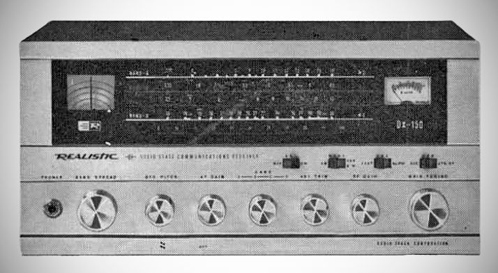
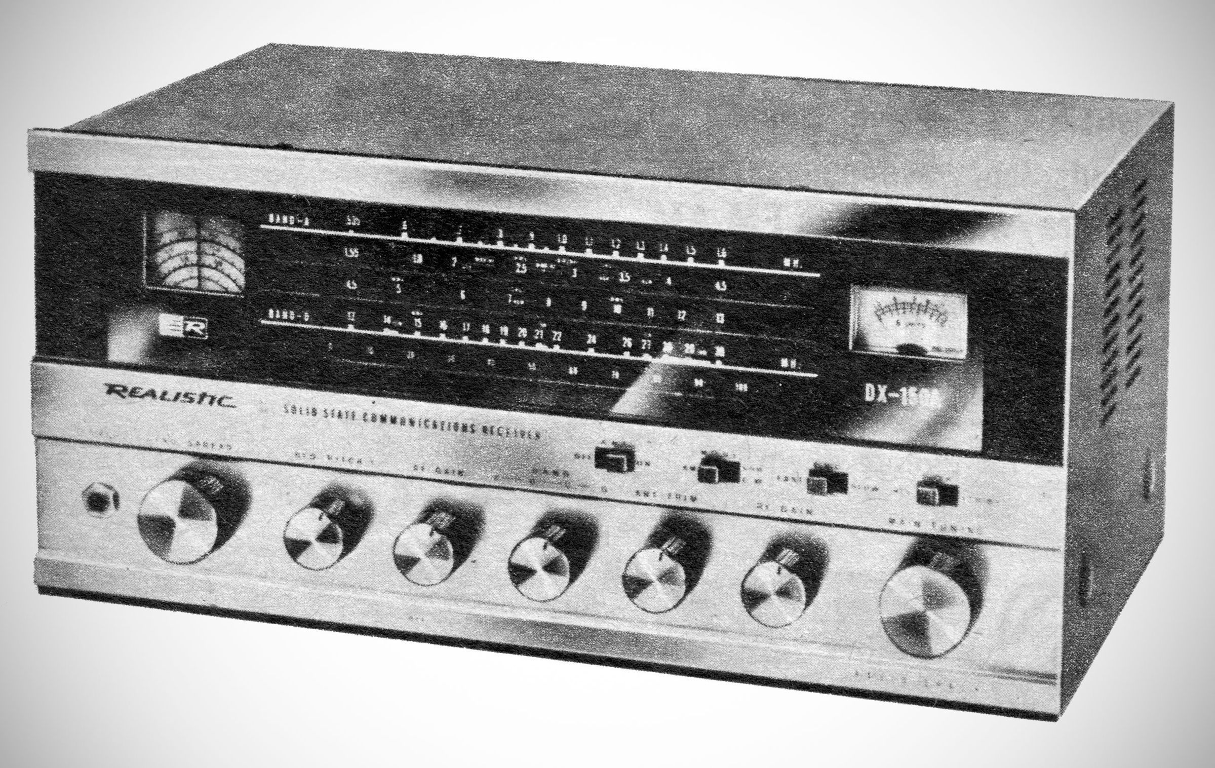
The DX-150 series was a general coverage receiver with coverage from 535 kHz to 30 MHz in four overlapping bands, with band spread for the 80–10 meter ham bands, and the 11 meter Citizens band. The receiver used a singled conversion scheme with an IF at 455 kHz.
The manuals for all three versions were practically devoid of useful specifications, but all versions are thought to be broadly similar. There were numerous circuit changes over time, but the high-level changes are these:
DX-150 (1967–1970) 17 transistors
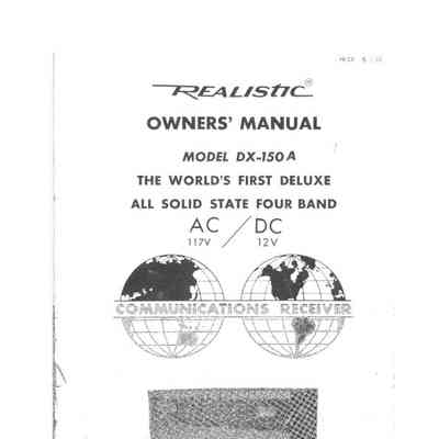
DX-150A (1970–1972) 15 transistors including a FET front-end
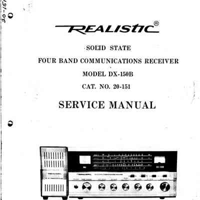
DX-150B (1972– 1977) 11 transistors including a FET front-end, 1 integrated circuit, and a mechanical filter
Features
– RF Stage: Features a cascode RF amplifier with a protective diode across Q1 to guard against strong overload signals.
– Noise Limiters: Includes both an IF noise limiter (Bishop-type) and an audio automatic noise limiter (ANL) for AM reception, switched simultaneously.
– AGC System: Dual-action AGC operating continuously, featuring selectable Fast and Slow release times (utilizing a 200 uf capacitor).
– Panel Controls: Features an S-meter, BFO pitch control, RF gain, audio gain, antenna trimmer, AGC time-constant switch, and a Receive/Standby switch.
– Dials: Dual string-driven dials (general coverage slide-rule dial and a circular bandspread dial) with negligible backlash.
Specifications based on QST's review of the DX-150
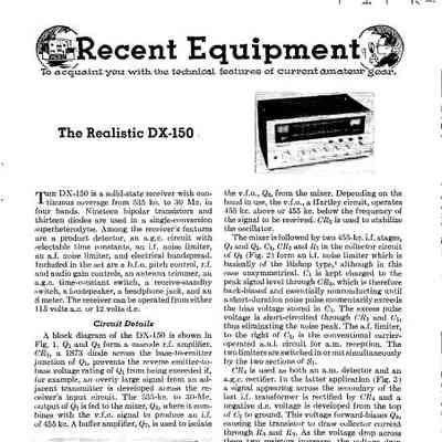
– Architecture: Single-conversion superheterodyne using 19 bipolar transistors and 13 diodes. ⚠️ Note: while the review says 19 transistors, the manual says 17. Also, this number varies with the specific model.
– Frequency Coverage: Continuous coverage from 535 kHz to 30 MHz across four bands, plus electrical bandspread for the Citizens Band and the 80–10 meter amateur bands.
– Intermediate Frequency (IF): 455 kHz.
– Modes: AM, SSB, and CW.
– Detectors: Standard diode detector for AM and a 4-diode bridge product detector for SSB/CW with a dedicated audio stage.
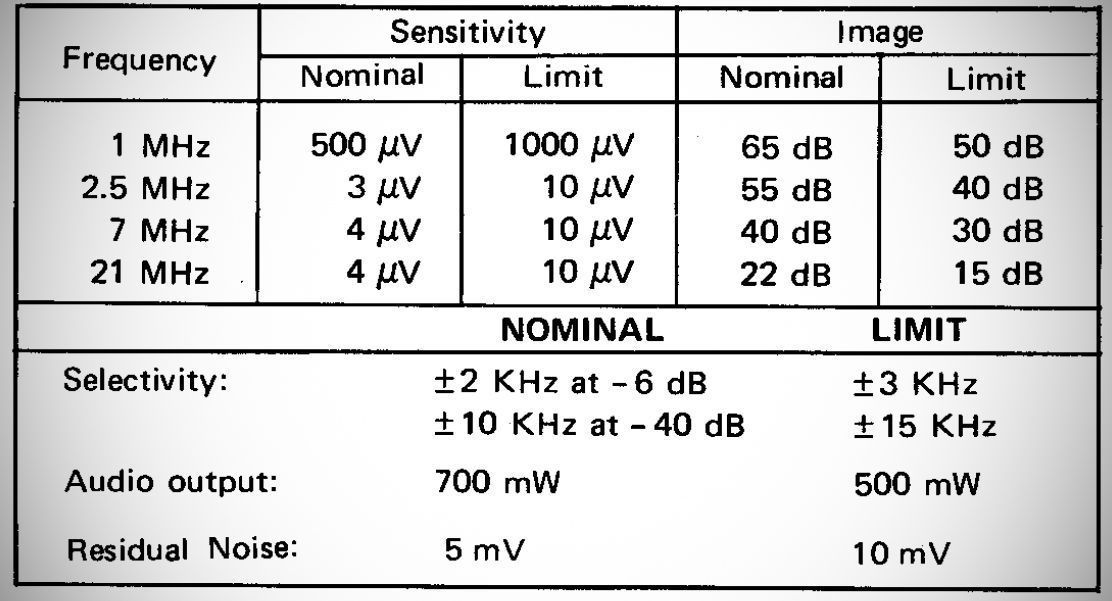
– Sensitivity & Drift: Good sensitivity for copying weak shortwave signals on a random-wire antenna; low frequency drift after a brief warm-up.
– Selectivity & Images: Image rejection ranges from 46 dB at 3.5 MHz down to 0 dB at 28 MHz, typical for a single-conversion design with a 455 kHz IF.
Limitations: Prone to cross-modulation from strong local signals (especially on the AM broadcast band). RF gain and antenna trimmer settings slightly affect main tuning. Mechanical shock/bouncing causes temporary frequency shifts.
Accessories
SP-150: Matching external communications speaker.
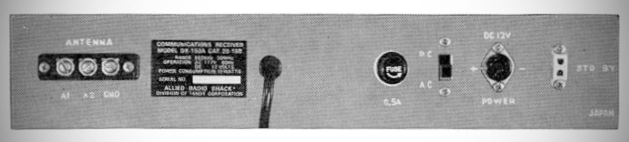
Power Requirements: 105–125 VAC, 50–60 Hz, or 12 V DC. Dial lights automatically disconnect during battery operation to conserve power. 6 watts.
12V DC Portable Power Pack: Holds eight 'D' cell batteries (rated for up to 100 continuous hours) or plugs into an auto cigarette lighter adapter.
References
Review: QST, Mar 1968, p. 39.
Review: Popular Electronics, Dec 1967, p. 75.
Review. Popular Electronics, Aug 1970, p. 78.
Brief description (DX-150B). Popular Electronics, Nov 1972, p. 30.