Note
QST, Jul 1945, p. 93.
QST, Apr 1946, p. 159. (improved with "Cal-O-Matic")
QST, May 1946, p. 125. (Newark ad with some details)
QST, Jun 1946, p. 159. (better noise limiter) (constantly improved but no "yearly models")
Lafayette catalog number 88 (1947, copyright 1946), p. 98.
QST, Feb 1947, p. 159.
Lafayette catalog number 89, p 173.
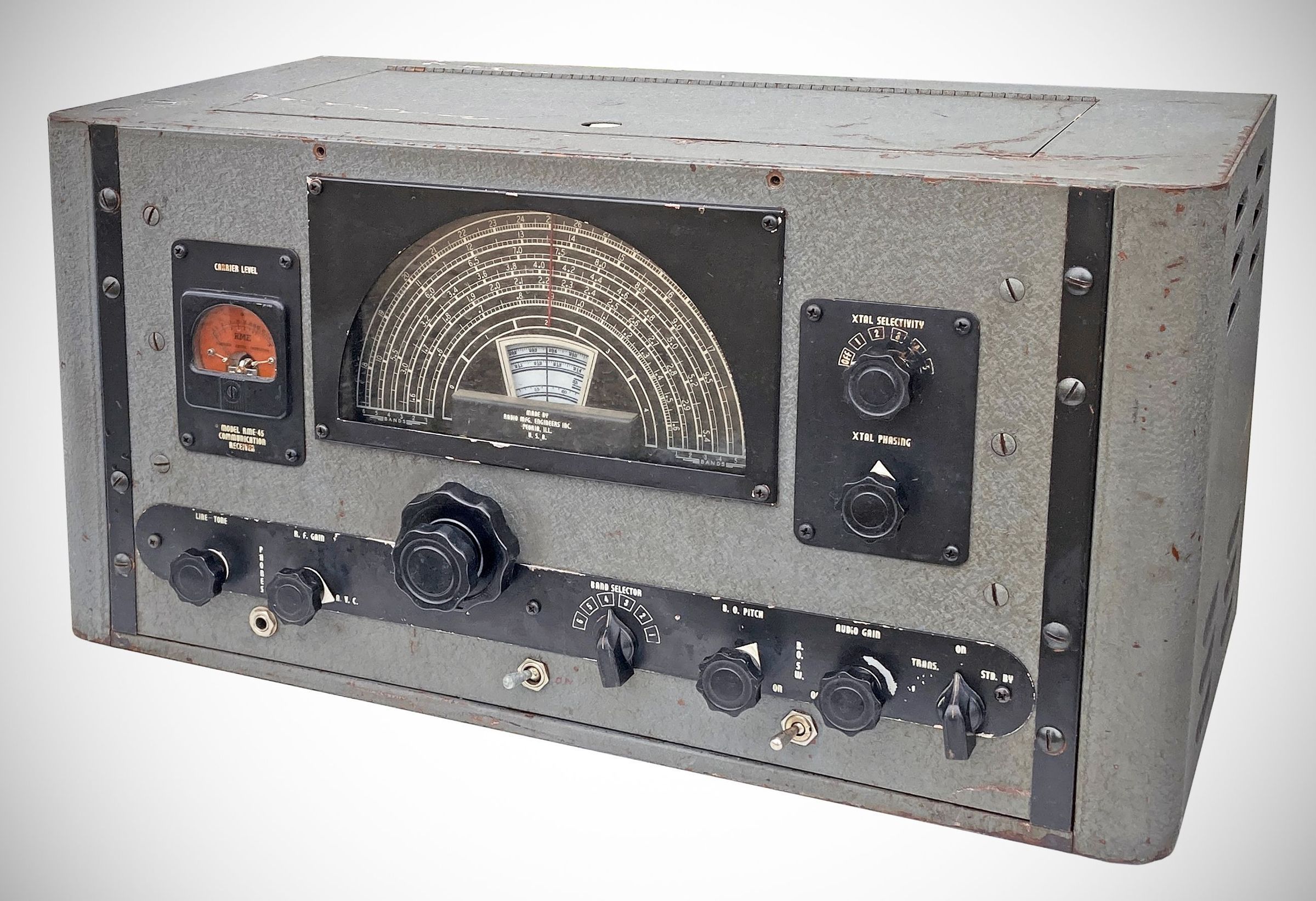
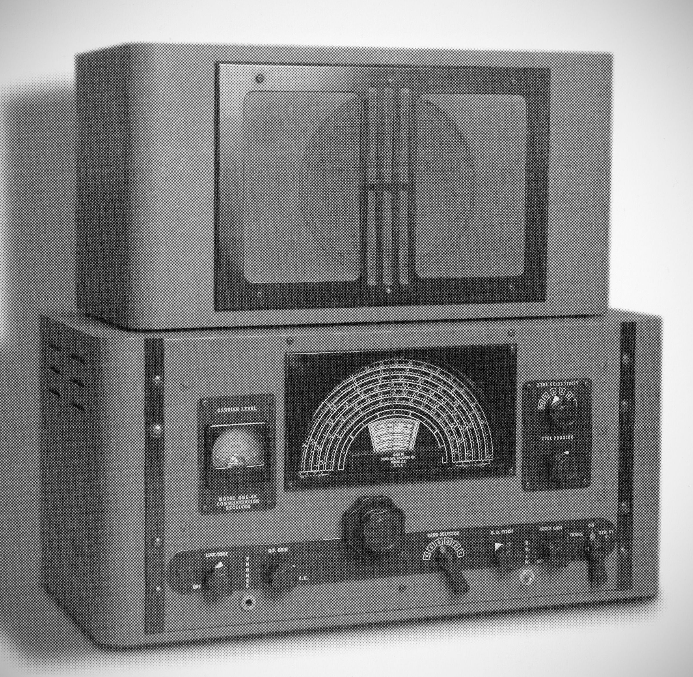
Radio Manufacturing Engineers' first post-war receiver (probably the first post-war receiver) built on the company's designs of the pre-war and war years. The initial model, the RME-45, was introduced in mid-1945. Early the following year, the Peoria, Illinois company released what is commonly referred to as the 45B, but never actually advertised that with that nomenclature. It should be noted that in advertising, RME said, "Constantly improved, but no yearly models.
The RME-45 is a 9(10)-tube (regulator in the "B" version) superheterodyne communication receiver designed for high-stability performance across six frequency bands.
The "45B" added "Cal-O-Matic" two-speed tuning, a calibrated band spread for the ham bands, voltage regulation, and improved noise limiting.
The receiver's total tuning range spans from 540 kc to 33 MHz, divided into six bands with overlap.
Specifications
– Intermediate Frequency: 455 kHz
– Audio Output: 3 Watts
– Audio Frequency Response: 100 to 5,000 Hz (±2.5 db)
Power Consumption:
Standard model: 115 VAC. 50/60 Hz, 90 watts
Universal 115/230 VAC model was available on special order)
Vacuum Tube Lineup
– 7B7: R.F. Amplifier
– 7S7: Converter
– 7B7: 1st I.F. Amplifier
– 7B7: 2nd I.F. Amplifier
– 7C7: Beat Frequency Oscillator
– 7A6: 2nd Detector & Automatic Noise Limiter
– 7C7: 1st A.F. Amplifier
– 7C5: Output Amplifier
– 5Y3G: Rectifier
– VR-150: Voltage Regulator (in "B" version only)
---
Features
Cal-O-Matic Two-Speed Tuning System (in "B" version only).
– Instead of a separate bandspread condenser—which RME eliminated to reduce RF circuit losses and increase stability—the RME-45 utilizes a two-speed coaxial tuning mechanism. It relies on a preloaded, backlash-free gear train where the smaller, fine-tuning knob rotates approximately five times for every single rotation of the larger knob.
– Five amateur bands are directly calibrated on the bandspread dial.
– For general logging, it uses a system pairing the main megacycle scale (split into half-circle sections 0 through 4) with 100 equal divisions on the inner bandspread dial, allowing operators to easily log and precisely return to any arbitrary frequency.
– Crystal Filter: Equipped with a variable selectivity crystal filter. The "XTL SELECTIVITY" knob ranges from OFF to position 1 (broad crystal, suitable for phone reception) up to 5 (razor-sharp, for CW reception).
– Crystal Phasing: A dedicated control is provided to minimize background noise or "null out" adjacent interfering signals.
– B.O. Switch & Pitch: A toggle switch activates the Beat Frequency Oscillator (B.F.O.) for CW reception. Flipping this switch to "ON" automatically disables the AVC (Automatic Volume Control) circuit. The BFO pitch is adjustable via the "BO PITCH" control.
– Carrier Level Meter: An S-meter is included to read relative signal strength in decibels and standard units. The meter functions accurately only when the RF Gain control is rotated fully clockwise to the "AVC" position.
– Automatic Noise Limiter (ANL): Automatically adjusts itself for maximum effectiveness. Because it can introduce slight audio distortion, it can be bypassed by pulling "OUT" on the audio gain control knob.
– Stand-By Switch: Features a three-position switch: On (normal operation), Standby (silences the receiver), and Trans (silences the receiver and closes an external relay circuit to control an associated transmitter).
– Speaker: ⚠️The receiver must never be turned on without its speaker plugged into the 5-prong socket on the rear apron. The voice coil impedance is 6 ohms (or 10kΩ if supplied with an electro-dynamic speaker utilizing a field coil).
– Antenna ("A-A-G"): Ships with a jumper between one "A" terminal and "G" (ground) for standard 50-to-75-foot single-wire antennas. The jumper is removed when utilizing a double-wire feeder system.
– Break-In Terminals ("B" and "R"): The "B" terminals are in series with the plate supply and must be shorted (via a jumper or transmitter relay) for the receiver to function. The "R" terminals are auxiliary relay contacts that short out when the front-panel switch is set to "Trans".