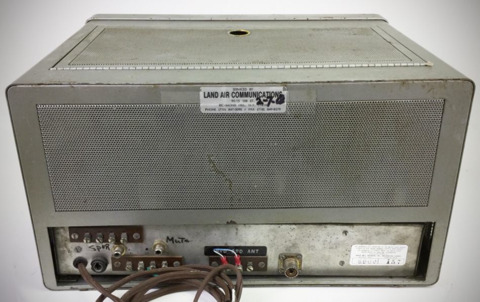
Note
QST, Nov 1959, p. 109.
More info: QST, Nov 1960, p. 111.
QST, Mar 1962 p. 139. (specs)
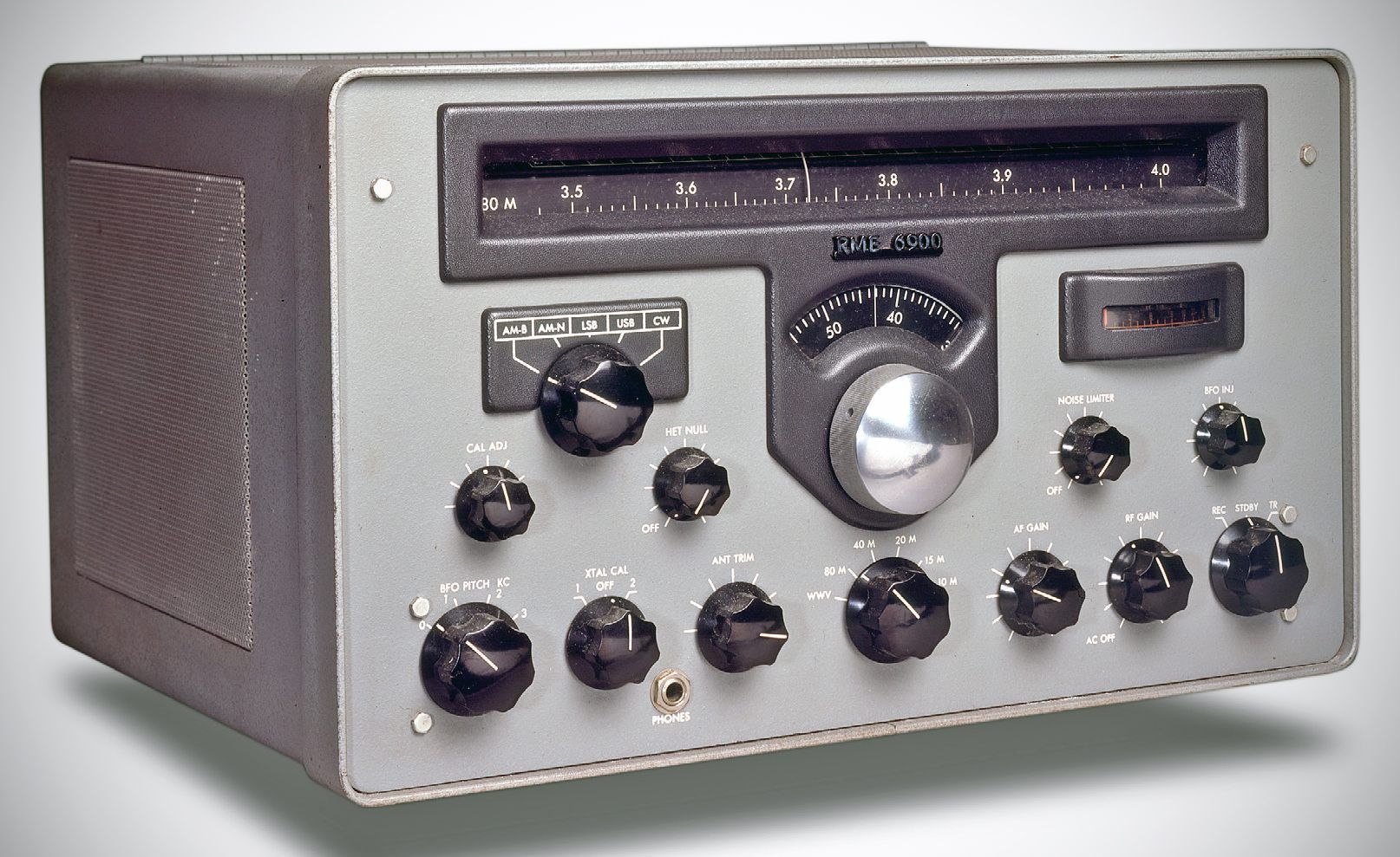
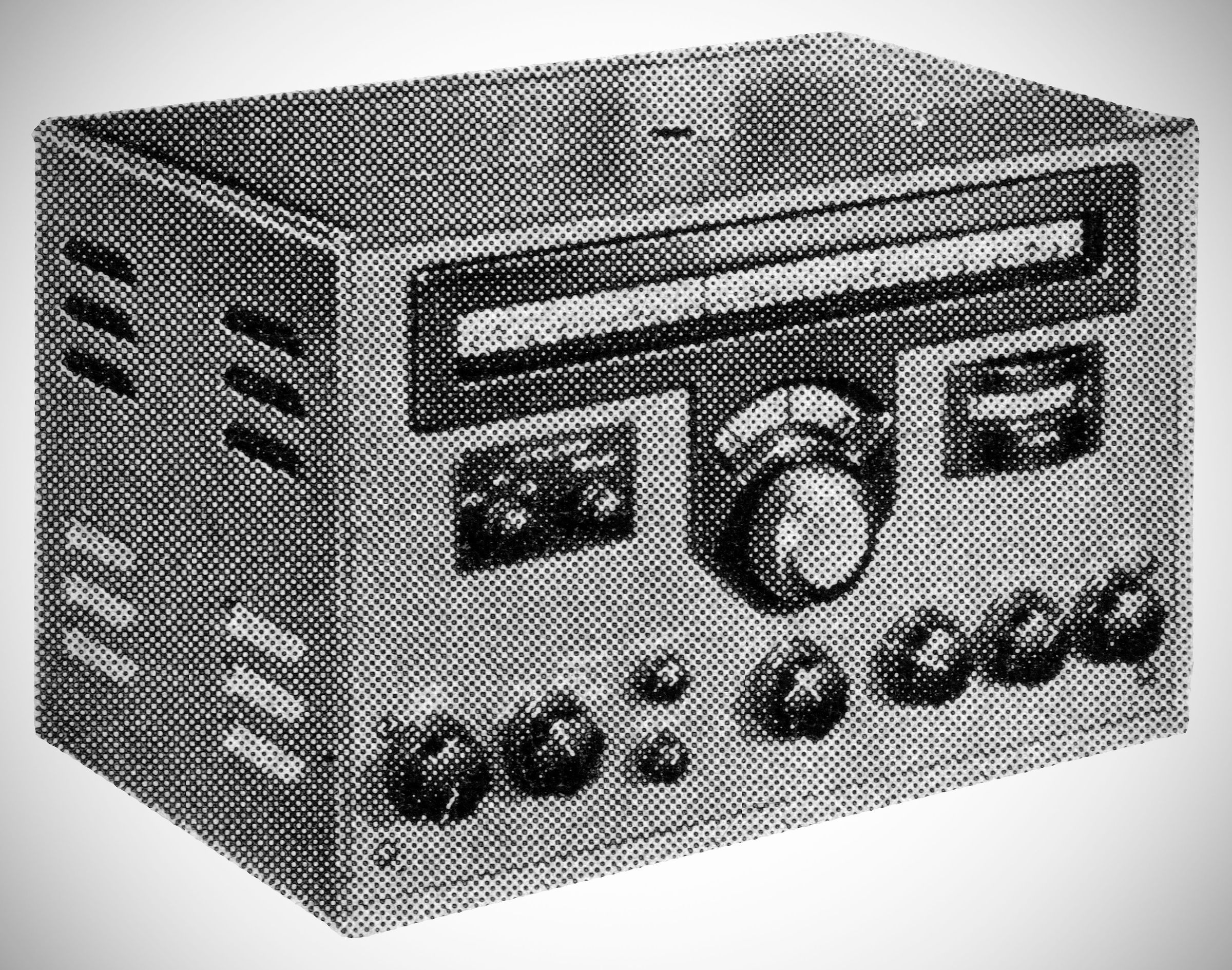
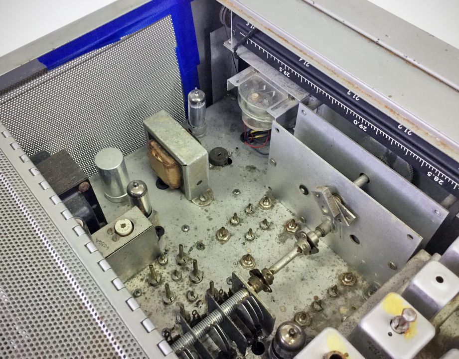
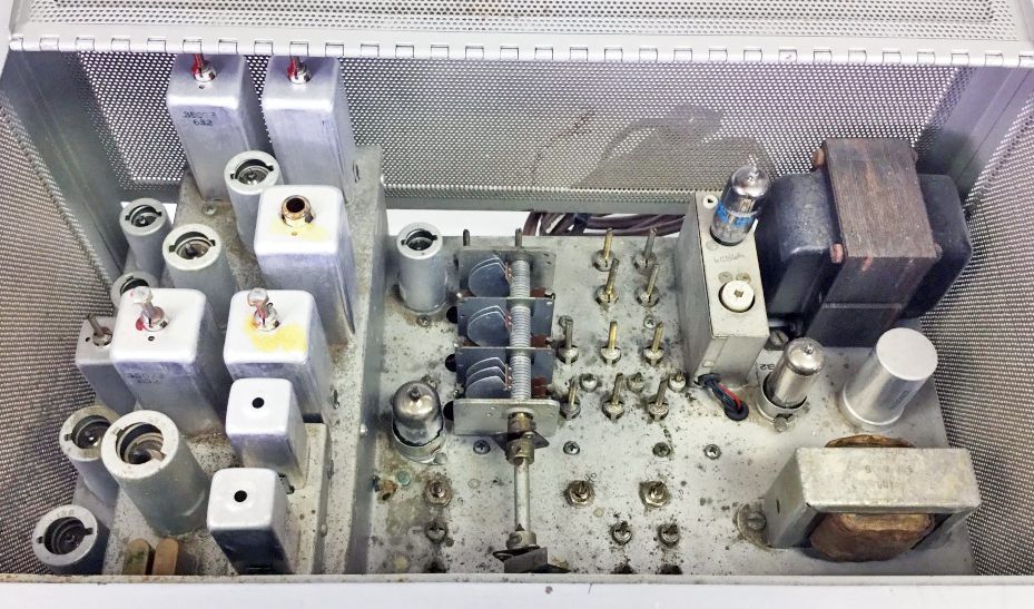
The RME 6900 covered the 80–10 meter ham bands and also had a band at 10 MHz for WWV. It used a tee-notch filter and 57 kHz IF for selectivity. The 12-tube, double-conversion receiver included a crystal calibrator, a product detector, and fast-attack AVC circuit.
Features
Coverage: Covers the 80 through 10 meter amateur bands (3.5–4.0 MHz, 7.0–7.3 MHz, 14.0–14.4 MHz, 21.0–21.5 MHz, and 28.0–29.7 MHz), plus 10.0–11.0 MHz for WWV.
Uses a dual-conversion circuit with a 1st IF at 2195 kHz and a 2nd IF at 57 kHz.
Modemaster Selector Switch: Integrates five operating modes:
– AM-Broad (AM-B): 3.6 kHz bandwidth at 6 dB attenuation, using dual-diode detection and conventional AGC.
– AM-Narrow (AM-N): 2 kHz bandwidth for operating in crowded band conditions.
– Lower Sideband (LSB): 2 kHz bandwidth using a product detector and a modified Fast Attack / Slow Decay AGC circuit. High-frequency and beat-frequency oscillators automatically position for LSB.
– Upper Sideband (USB): 2 kc bandwidth configured for USB, or for CW net operation where AGC and a broader passband are desired.
– CW: 500-cycle bandwidth at 6 dB attenuation, AVC disabled, and BFO Pitch/Injection controls enabled.
Heterodyne Null ("T-Notch"): A continuously variable notch filter operating across the IF passband, offering greater than 40 dB rejection to notch out interfering heterodynes.
Noise Limiter: An IF-stage dynamic noise limiter (operating at the IF level rather than standard audio clipping) using a 6AL5 tube.
Crystal Calibrator: Built-in 100 kHz calibrator with a two-position switch. Position 1 feeds the marker signal to the receiver with the antenna attached; Position 2 automatically disconnects the antenna from the input stage so high harmonic marker signals (200th–300th) can be spotted cleanly without QRM.
BFO Controls: Features separate BFO Pitch and BFO Injection controls for optimizing weak CW signal reception.
Main Tuning: Features a 54:1 tuning ratio drive mechanism.
Specifications
– Sensitivity: 1 microvolt (30% modulation) for 50 mW audio output.
– Signal-to-Noise Ratio: 10 dB at 1 microvolt input (30% modulation).
– Frequency Drift: Under 0.005% after a 15-minute warmup period.
– Image Ratio: Not less than 56 dB on any band.
– Audio Output: 1.0 watt maximum into isolated 4-ohm and 500-ohm rear-terminal outputs (suitable for phone patch or anti-trip VOX operation).
Tube Lineup
– 6BA6: RF Amplifier, 1st 57 kHz IF Amp, 2nd 57 kHz IF Amp.
– 6U8A: 1st Mixer & Stabilized Oscillator (Triode/Pentode).
– 6U8A: 2nd Mixer & Crystal Oscillator (Triode/Pentode).
– 6C4: 1st IF & "T" Notch Driver.
– 6AL5: Dynamic Noise Limiter.
– 6T8: Full-wave 2nd Detector, 1st Audio, and AGC Line Charging Diode.
– 6AQ5A: AF Power Output.
– 12AT7: Product Detector & Beat Frequency Oscillator (BFO).
– 6CB6: 100 kc Crystal Calibrator Oscillator.
– OB2: Voltage Regulator.
– (2) 1N1763: Silicon Power Rectifiers.
Power requirements
117 VAC, 50/60 Hz, 55 watts.