Note
QST, May 1975, p. 4.
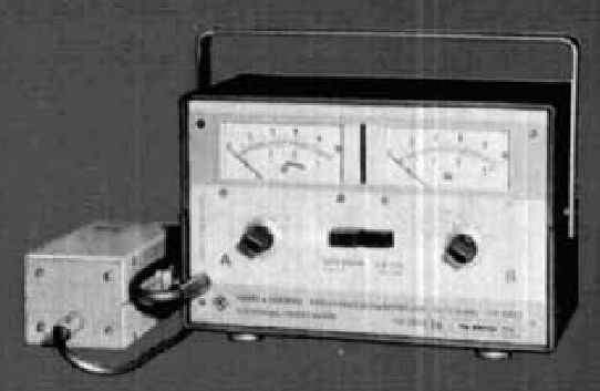
The Rohde & Schwarz directional rf power meter provides simultaneous measurement of incident and reflected power over the frequency range from 25 to 1000 MHz without any switching or changing measuring heads. The indication accuracy of the power meter i s within 4% of the reading and ±1% of full scale. this is a significant improvement over the accuracy of most RF power meters which is usually specified only as a percentage of full-scale deflection.
Although the meter is designed for operation over the range from 25 to 525 MHz, it is usable to 1000 MHz. If desired, the factory can calibrate the instrument to 1500 MHz at slight additional charge.
Power ranges are 3.2, 10, 32, 100, and 320 watts full scale.
The meter consists of two units: the measuring head, and the indicating unit. The measuring head contains a symmetrical directional coupler which measures both incident and reflected power. Networks within the measuring head compensate for the voltage coupled out, which rises with frequency. The coupling attenuation and voltage division in the directional coupler are adjusted so that the RF rectifying diodes operate only in the square-law region. This permits the use of easy- to-read, linear meter scales.
The small rectified voltage (10 uV to 25 mV) from the directional coupler is amplified in a chopper amplifier which converts the dc input voltage to a square wave which is boosted 50 dB in a series-connected amplifier. The amplified signal i s then applied to an attenuator which is ganged with another attenuator in the feedback path.
In the 3.2 watt position attenuation is 0 dB, increasing 10 dB with each measurement range. Since the attenuation in the feedback path is reduced simultaneously in corresponding amounts to the main attenuator, the loop gain of the chopper amplifier i s the same on all measurement ranges so the meter indications are free of oscillation and transient response remains constant.
The attenuator is followed by the final amplifier where the signal is boosted by another 50 dB and then fed to a synchronous detector. The transistors in the synchronous detector are driven together with the same square-wave generator which drives the chopper amplifier. The synchronous detector operates into a charging capacitor; a series resistor is included to form a low-pass filter with a low cutoff frequency.
The voltage at the output of the lowpass filter (approximately 300 mV on all measurement ranges for full-scale deflection) is connected to the panel meter. The feedback voltage to the chopper amplifier is fed back through a thermistor which compensates for the slight temperature effect on the RF rectifying diode in the directional coupler. Temperature effect on the meter indication is less than 0.25% (referenced to indication at 25ºC).
Although the directivity of the directional coupler is 30 dB or more above 30 MHz, finite reflected power would be indicated when working with matched terminations. The designers compensated for this effect by connecting the inverting output of one channel to the non-inverting input of the other channel through resistors. The rectified voltage of the incident power being measured in channel A is attenuated such that the voltage available at the inverting input of the channel B chopper (reverse power channel) is virtually the same as the voltage present at the non-inverting input which develops because of the finite directivity of the directional coupler. The two voltages balance out and, as a result, there is no indication on the reflected power meter.
The effect is the same as if the measurement were made with a match-terminated directional coupler with infinite directivity.
The meter is available for 50, 60, or 75 ohms. Various types of connectors
are available including type N, BNC and UHF, and may be changed in the field.
The built-in power supply uses five 1.5-volt D-size cells with an estimated operating life greater than 7000 hours (total power drain is 1 mA or less depending upon the measurement range). The VSWR of the measuring head is 1.03 or less, and insertion loss up to 300 MHz is 0.1 dB or less (0.25 dB or less to 525 MHz).
Accuracy is within 5% of full scale and frequency response is flat within 3% over the range from 1.5–30 MHz. Reflection due to the coupling system is less than 2%.