Note
QST, Jan 1964, p. 141.
QST, Aug 1964, p. 123.
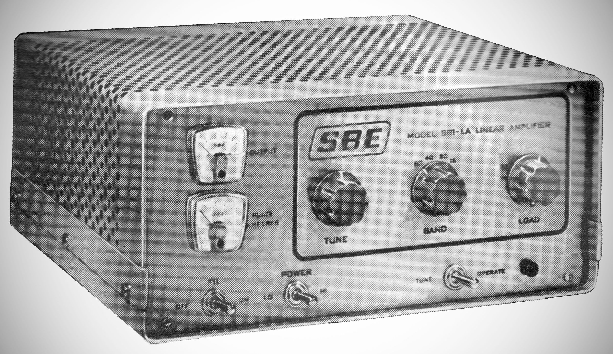
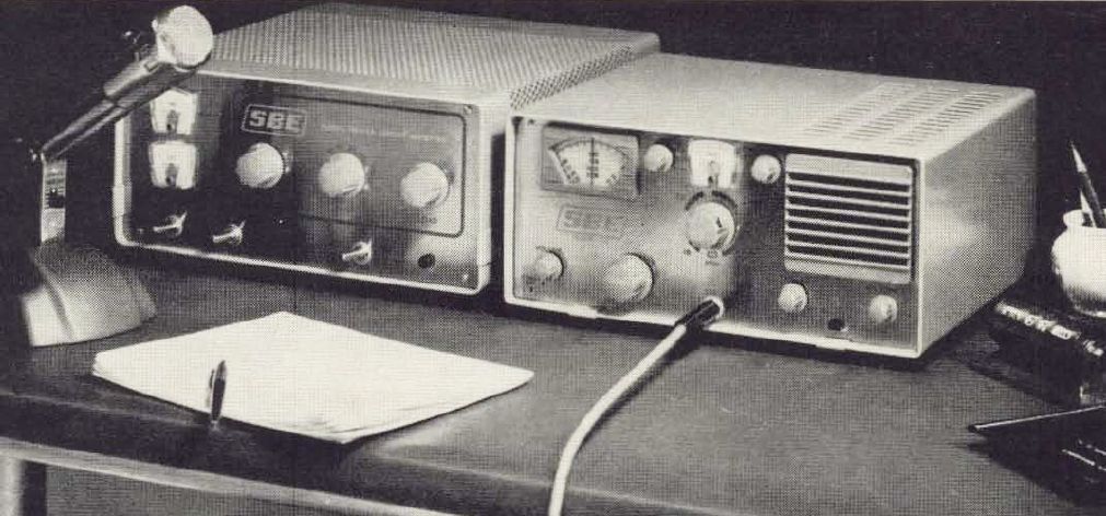
The SB1-LA is a compact, desktop single sideband linear amplifier manufactured by Sideband Engineers (SBE) of South San Francisco, California. Introduced late in 1963 as a companion unit for the SBE SB-33 transceiver, it was engineered to accept roughly 65 watts of drive power and operate across the amateur bands from 80 through 15 meters (3.8 to 21.5 MHz).
The unit is notable for housing a full high-power amplifier and internal AC power supply inside a single package measuring 5.375 inches high by 12 inches wide by 12 inches deep, weighing only 35 pounds. Visually, it matches the SB-33 transceiver with a gray cabinet, satin chrome front panel, and light blue knobs and trim.
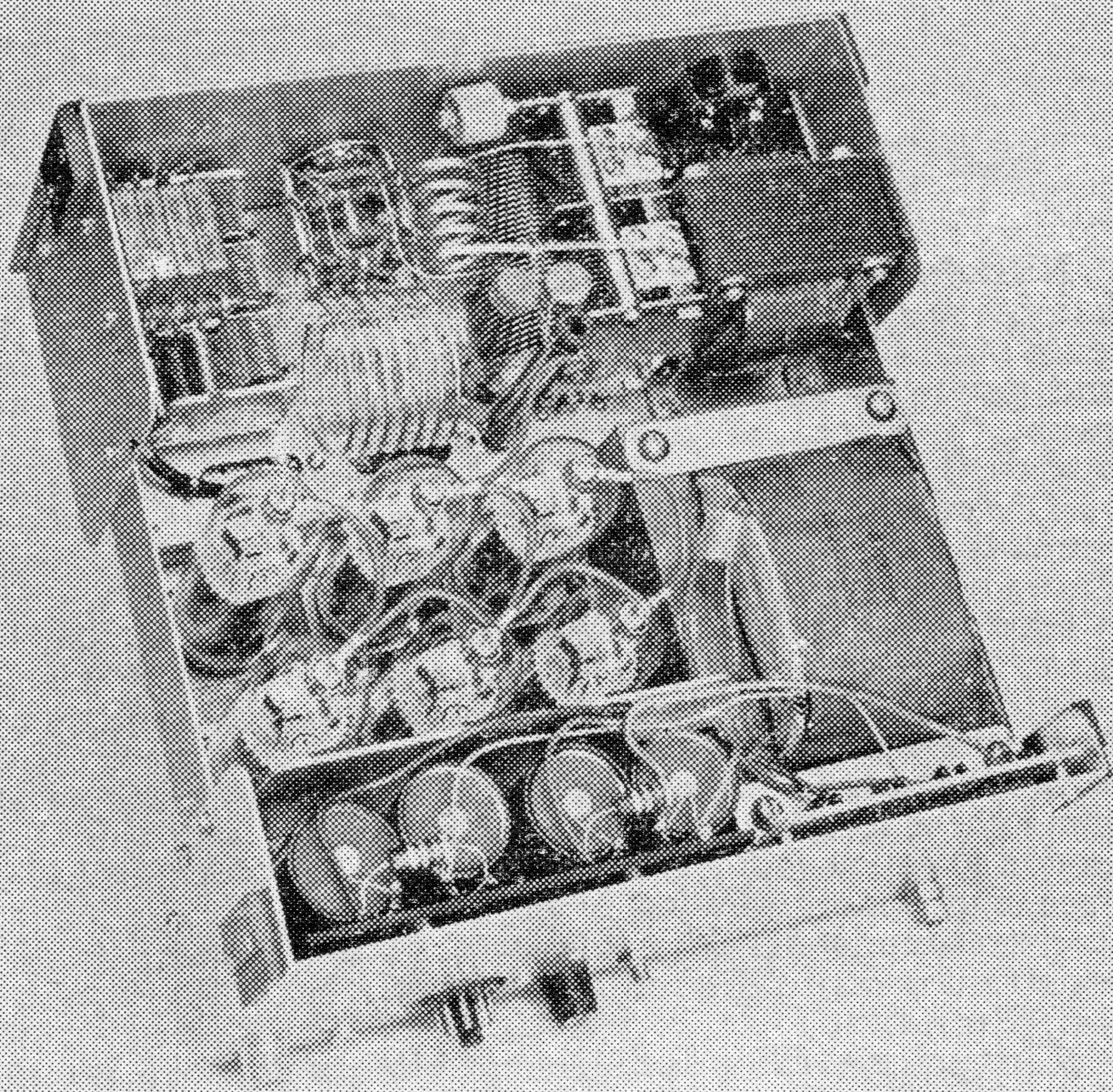
Rather than using a single large power tube, the SB1-LA uses a bank of six 6JE6 television sweep tubes connected in parallel. Operated in Class AB1 grounded-cathode service, this high-perveance arrangement allows the amplifier to run at a low plate voltage of around 800 VDC while drawing up to 1.2 to 1.5 amperes under load.
Driven without grid power requirements in Class AB1, the amplifier uses a set of swamping resistors connected across the grid input to present a 75-ohm resistive load to the driving transceiver. Individual 27-ohm parasitic suppression resistors are installed in each tube's grid lead.
A low-impedance pi-network output stage matches the paralleled tubes to a 50-ohm unbalanced load (SWR up to 2:1). Due to the low plate load impedance, the tank circuit uses a large variable tuning capacitor and a small inductance (the 80-meter coil uses only 7 turns). Switching the band selector automatically taps the coil and switches supplementary shunt capacitors across the TUNE and LOAD controls on 80 and 40 meters.
Power Ratings: The SB1-LA is rated for 1000 watts PEP input on SSB (reduced to 750 watts PEP on 15 meters). On CW, FM, and FSK, it is rated for 400 watts input, and 300 watts on AM.
The built-in power supply relies on a single power transformer feeding two semiconductor voltage-doubler circuits connected in series to yield the 800 VDC high-voltage bus, allowing the use of compact filter capacitors. A third secondary winding provides fixed grid bias, which is rectified by semiconductor diodes and adjustable via a potentiometer on the rear apron. Standby bias cuts off the tubes completely when receiving to prevent tube hash noise.
For mobile operation, SBE offered the optional model SB3-DCP DC-to-AC inverter to power the unit directly from a 12-volt vehicle battery system.
Specifications
– Bands: 80-40-20-15 meters.
– Power rating: 1000 watts PEP input. (750 watts 15 meters). 400 watts AM.
– Drive requirements: Approx. 75 watts for full rated output.
– Input impedance: 50 ohms resistive.
– Output impedance: (antenna) 50 ohms, unbal. VSWR 1.5 or less.
– Power supply: Built-in all solid-state, 117V AC.
Tube Lineup:
(6) 6JE6. (parallel connected).
Power requirements: 115V AC @ 12A max, at peak output. (DC) Standby: 12.6V (nom) @ 7.5A. Peak: 12.6V @ 110A.
References
Brief description. Electronics World, May 1964, p. 85.
Review: QST, Sep 1964, p. 86.