Note
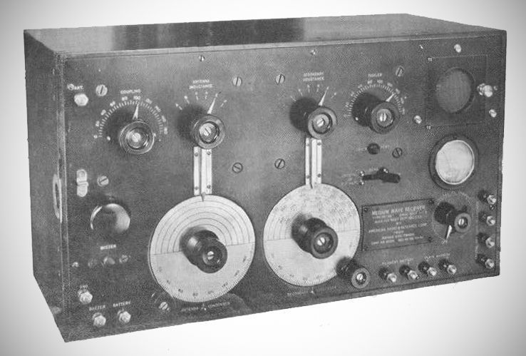
The receiver line had a Naval origin, designed by the Bureau of Steam Engineering. The SE-1420 design (an off-shoot of the SE-143) featured heavy design contributions from Radio Aides Priess and Lester Jones. At the time, it was officially praised by the Navy as "the best receiver for general radio reception that the Service, and probably the world, has ever seen."
Designed in 1918, the SE-1420 entered full production in 1919. Three companies built them for the Navy: Wireless Specialty Apparatus Co. (400 sets), Sperry Gyroscope Co. (300 sets), and American Radio & Research Corp. (400 sets).
Directly after World War I, Wireless Specialty Apparatus Co. slightly modified the Navy's SE-1420 design for commercial and marine use, releasing it in 1919 under the designation IP-501. It was later sold by RCA for $550.
Technical Specifications & Features
– Tuning Range: The original version covered a wavelength range of 235 to 7,500 meters. This was later standardized to 250 to 8,000 meters (1200 kHz to 37 kHz) , though adding loading coils could increase the range up to 21,000 meters.
– Coupling & Coils: It is a two-circuit, inductively-coupled receiver. The coils are bank-wound using high-frequency Litzendraht (Litz) wire.
– Shielding: The primary and secondary circuits are thoroughly shielded from external interference and one another by heavy sheet-copper boxes.
– Components: It features balanced-rotor type condensers with heavy Bakelite discs for end plates. The rigid copper connecting wires are covered with varnished cambric tubing (spaghetti).
– Dials: One half of the tuning dials is calibrated in 180 divisions, while the other half features six semicircles for hand calibration matching the 6-position switch pointers.
– Tubes: Early 1919 manuals recommended using SE-1444, CW-933, or CG-890 vacuum tubes, while the UV-201(A) became popular in the 1920s.
– Controls: A panel meter was used alongside a rheostat to set the filament voltage to the proper current. The plate required 30 to 45 volts.
– Emergency Crystal Detector: An interesting safety feature allowed operators to instantly switch to a backup crystal detector if a vacuum tube or battery failed.
The Navy implemented several minor structural modifications:
SE-1420 (Original): Features a built-in audion detector with inductive feedback ("tickler") and an adjustable bridging condenser knob switch to select bypass capacities around the headphones.
SE-1420C: Replaced the adjustable knob switch with a fixed-capacity .007 mfd bridging condenser (with an engraved nameplate covering the old knob location).
SE-1420D: Features an adjustable bridging condenser and additional non-connected binding posts.
SE-1420E: Same as the 1420C, but includes extra "crystal" binding posts and two sets of detector battery binding posts in parallel (with no active connections to the receiver circuits).
SE-1420F: Same as the 1420C, but retains the adjustable bridging condenser switch.
Commercial Variations (IP-501 series)
IP-501 (1919): Added binding posts and links in the primary, secondary, and tickler circuits so operators could insert external loading coils. Early versions required an outboard audio amplifier.
IP-501A (1922): This late commercial variant integrated two additional stages of audio amplification directly into the set and added an output filter, differentiating it from the earlier models.