Note
QST, May 1979, p. 107.
QST, Jan 1980, p. 99.
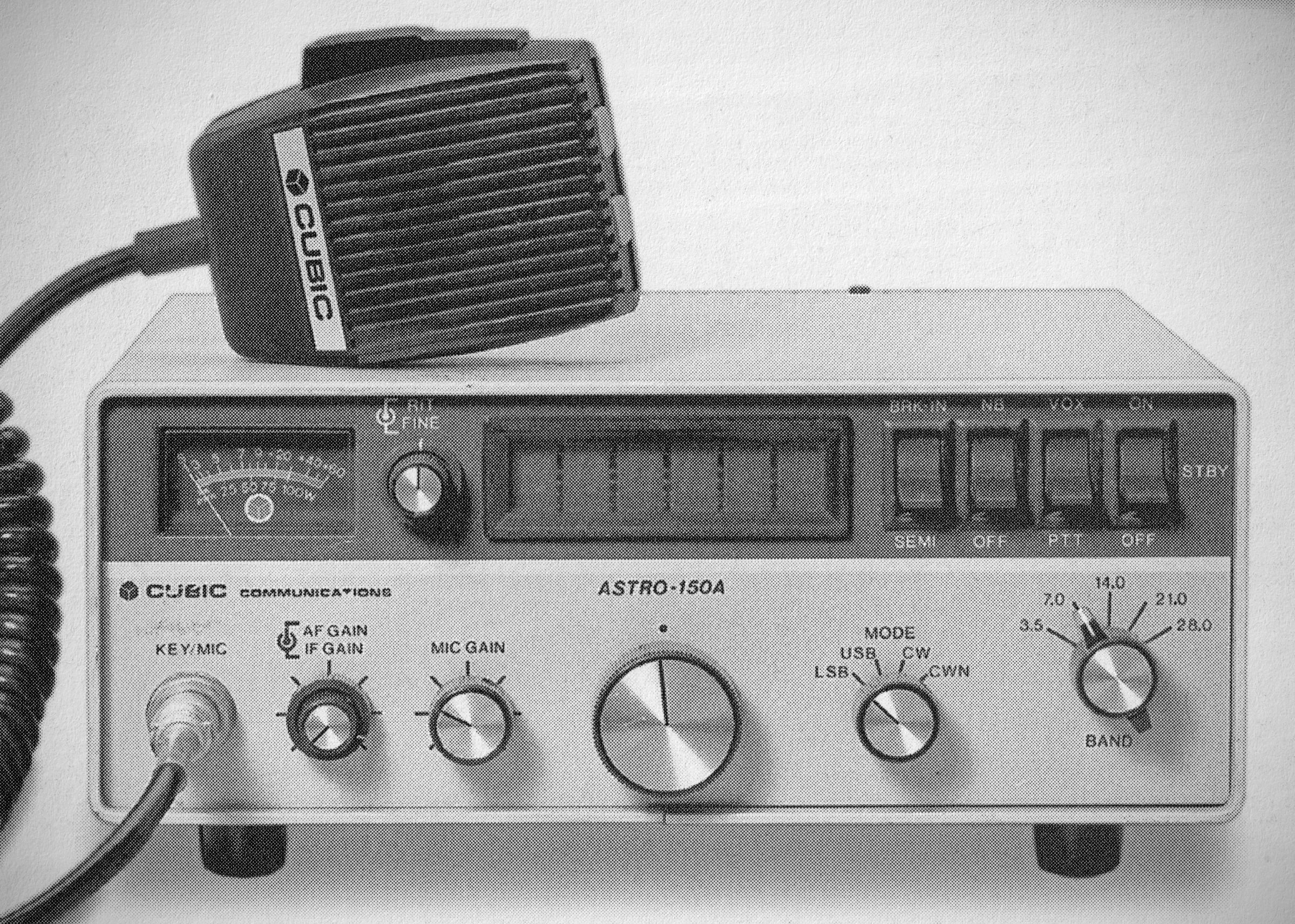
QST, Sep 1980, p. 131. (150A, now from Cubic)
QST, Apr 1981, p. 183.
QST, Jul 1981, p. 135.
QST, Mar 1982, p. 128. (close out)
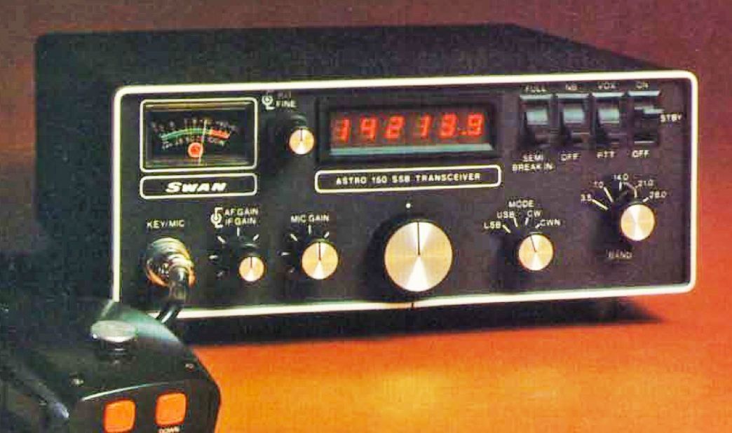
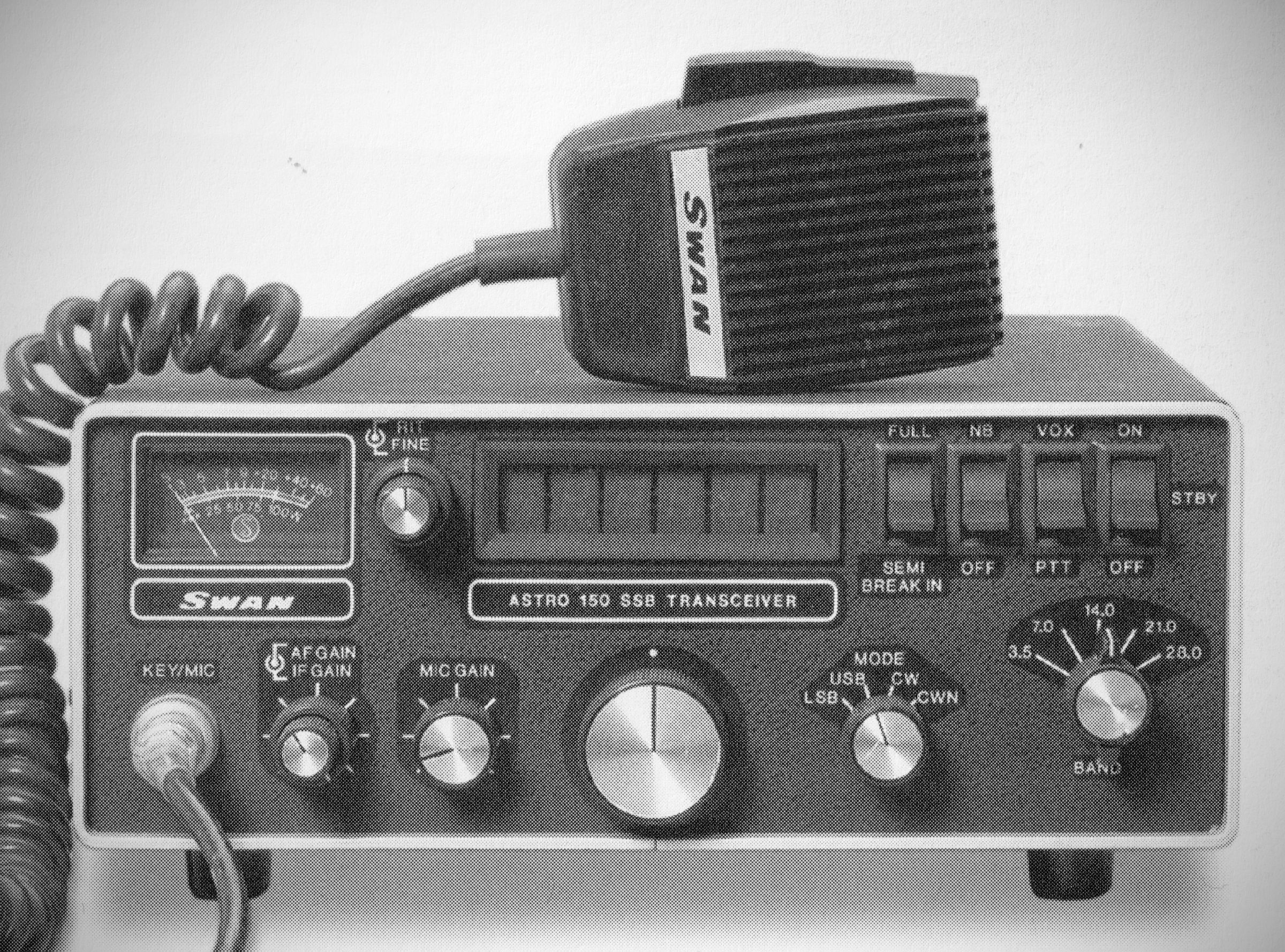
The Swan Astro-150 is a compact, solid-state, single-conversion transceiver covering the 80 through 10-meter HF bands for SSB and CW operation. Powered by a Signetics LSI microprocessor chip, the synthesizer remembers the last frequency tuned on each band (retained via a special "memory-only" power switch setting). The synthesizer allows out-of-band reception for MARS operation and shortwave listening (such as WWV on 15 MHz via the 20-meter band position).
The Astro 151 version of the 150 added 160 meter coverage in lieu of 10 meters.
The transceiver is built as an extremely compact unit intended for both fixed-station and mobile use. Internal construction features nine double-sided glass-epoxy circuit boards with modular, unplugable wiring harnesses and controls soldered directly to a single front-panel board.
Instead of a conventional optical encoder or main tuning dial, tuning is controlled via a center-detented potentiometer knob (Swan called it Variable Rate Scanning , or VRS) that slews the frequency upward or downward at a rate proportional to how far the knob is turned (ranging from 200 Hz to 100 kHz per second).
The 150(151) ncludes a fine-tuning control (±75 Hz) and a continuous Receiver Incremental Tuning (RIT) control with a narrow ±300 Hz range.
The included hand-held microphone features top-mounted "up" and "down" buttons for frequency adjustments in 100-Hz steps or smooth scanning at 1 kHz/second when held.
Broadband band-pass filtering eliminates the need for receiver peaking or transmitter tuning controls.
Features a double-balanced diode-ring passive mixer following a three-section band-pass filter, delivering excellent dynamic range and strong-signal handling against cross-modulation and intermodulation overload.
⚠️ Note: When changing bands, the synthesizer unlocks for a few seconds (muting the receiver and lighting all display decimal points); however, the transmitter is not automatically muted and will emit RF frequency sweeps if keyed while unlocked.
Features
– AGC: Uses audio-derived fast-attack/slow-decay AGC, though tested as having a slightly slow attack with noticeable "pumping" on strong signals.
– Full Break-in (QSK): Incorporates true CW full break-in operation utilizing a fast, quiet SPST reed relay for antenna switching. Semi-break-in mode is also switchable.
– Dual CW Selectivity: Includes a dedicated "narrow" CW filter option (approx. 500 Hz bandwidth) selectable from the front panel.
– ALC System: Built-in Automatic Level Control works alongside the internal peak-reading power meter to prevent overdriving on SSB and to control power output.
– VOX & Sidetone: Standard VOX and PTT operation, featuring independent VOX delay adjustments for CW and phone mode.
The unit lacks a front-panel headphone jack (only providing a rear-panel external speaker/audio output jack).
Specifications:
– Frequency Coverage:
160M: 1.8-2.4 MHz (Model 151 only)
80M: 3.0-4.5 MHz
40M: 6.0-8.3 MHz
20M: 13.8-16.0 MHz
15M: 20.8-23.0 MHz
10M: 28-30 MHz (Model 150 only)
– Frequency Control: Digital synthesizer with 100 Hz steps, plus fine and RIT controls.
– Modes of Operation: SSB with selectable sideband. CW with automatic 800 Hz offset on transmit and full or semi-break-in.
– Electromagnetic Interference:
Five element lowpass filter on each band.
Three pole bandpass filter on each band.
Receiver Specifications:
– Circuit Design: Single conversion to 9.0165 MHz IF using double balanced mixer. Exceptional immunity to overload and cross modulation.
– Sensitivity: S+N/N: 0.35 uV for 10dB Typical.
– Selectivity: Crystal bandpass 8 pole filter. Bandwidth 2700 Hz @ 6dB down, 4320 Hz @ 60dB down. 1.6 shape factor.
– Internally Generated Spurious Response: 0.5 uV equivalent input signal.
– AGC: 6dB change in audio level over input range of 1.5 uV to 1V (100dB).
– Audio Output: 3 Watt available @ 10% distortion, 300-3000 Hz, 4 ohms.
– Meter: S-Unit from 1-9, 20, 40, and 60dB over S-9.
Transmitter Specifications:
– Circuit Design: Excellent harmonic and TVI suppression. ALC limits SSB peak power and CW power to 100 watts.
– Power Input: 235 Watts PEP input at 13.8 VDC input.
– Power Output: 100 Watt PEP into 50 ohm non-reactive load at 13.8 VDC input.
– Unwanted Sideband Rejection: 60dB down at 1000 Hz audio.
– Harmonic Output: 50dB below peak power level.
– Carrier Suppression: 50dB below peak power level.
– Spurious Output: 50dB below peak power level.
– Transmit Control for SSB: PTT and VOX standard.
– CW Transmit: Full or Semi-break-in with sidetone standard. 800 Hz offset on transmit frequency.
– Microphone Input: 47K ohm input impedance.
– Audio Response: 300 to 3000 Hz ± 6dB.
– Meter: Reads peak power on transmit.
– Cooling: Large capacity heatsink fins supplied. For SSTV, RTTY, and semi-continuous transmit, forced air cooling such as a small muffin fan on heatsink fins required.
Power Requirements: 12-14 VDC negative ground only. No damage 10-15 VDC. 20 Ampere peak current.
References
Review. QST, Jul 1980, p. 41.