Note
QST, May 1966, p. 167.
QST, Sep 1966, p. 113. Some specs.
QST, Jan 1967, p. 119. (specs)
QST, Dec 1968, p. 131. (250C)
QST, Aug 1971, p. 109.
QST, Jun 1972, p. 133.
QST, Jan 1973, p. 109.
QST, Feb 1975, p. 109.
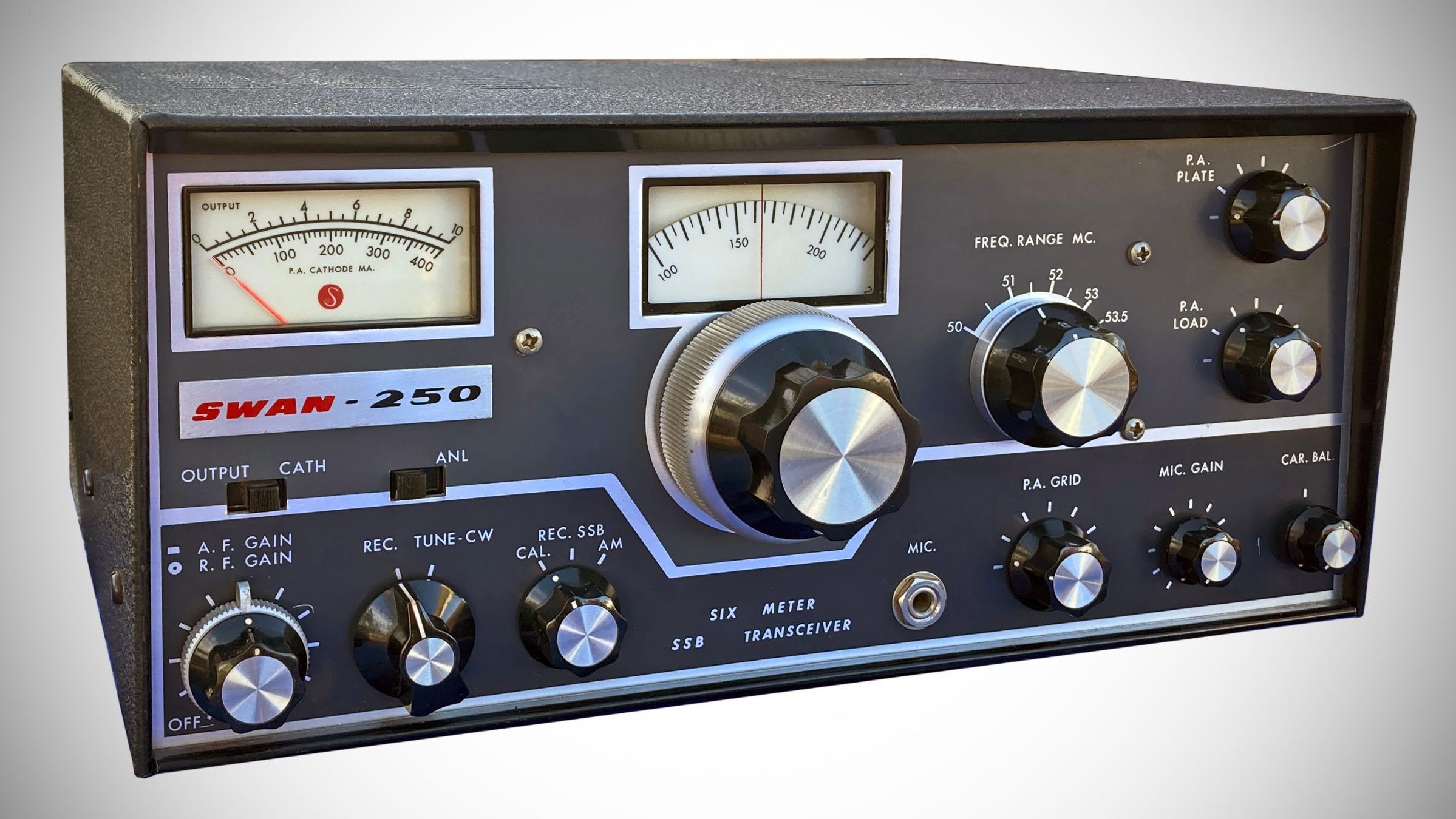
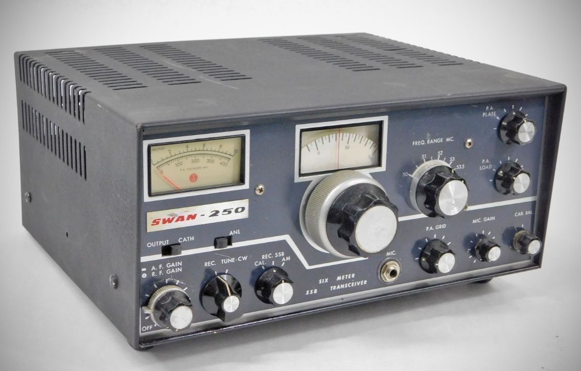
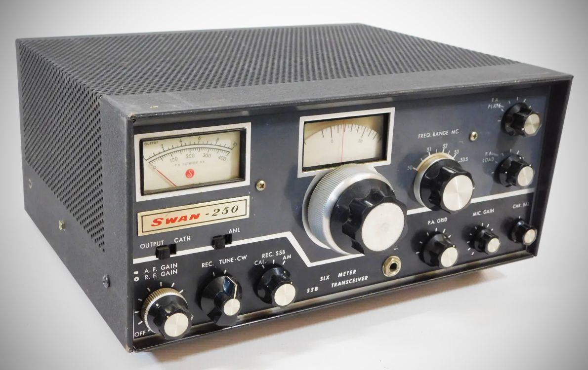
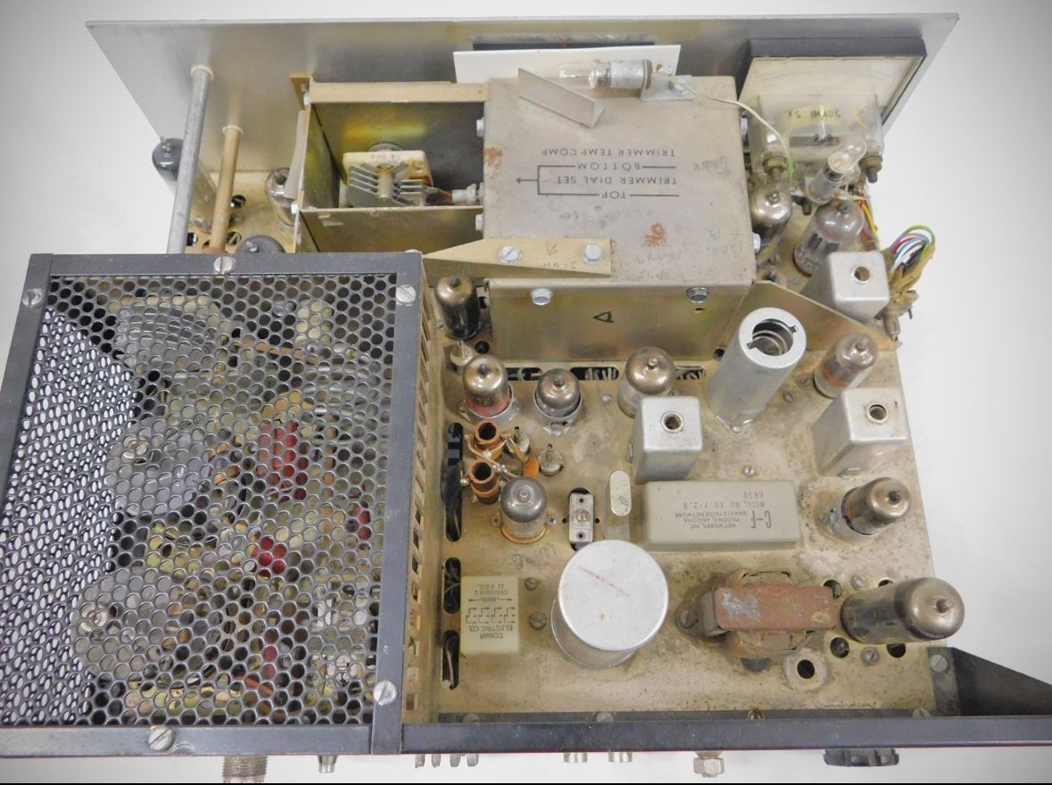
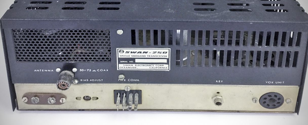
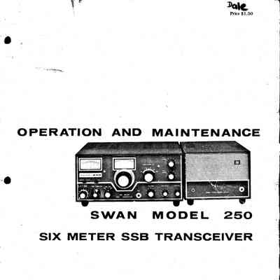
Introduced in 1966 by Swan Electronics, the Swan 250 was a single band hybrid transceiver dedicated to the 6-meter amateur radio band (50–54 MHz). Designed for SSB, CW, and AM operations, it brought high-power SSB operation to VHF enthusiasts at a price point ($325 at launch) lower than competing setups of its era. In ran 240 watts PEP input to a pair of 6146 finals.
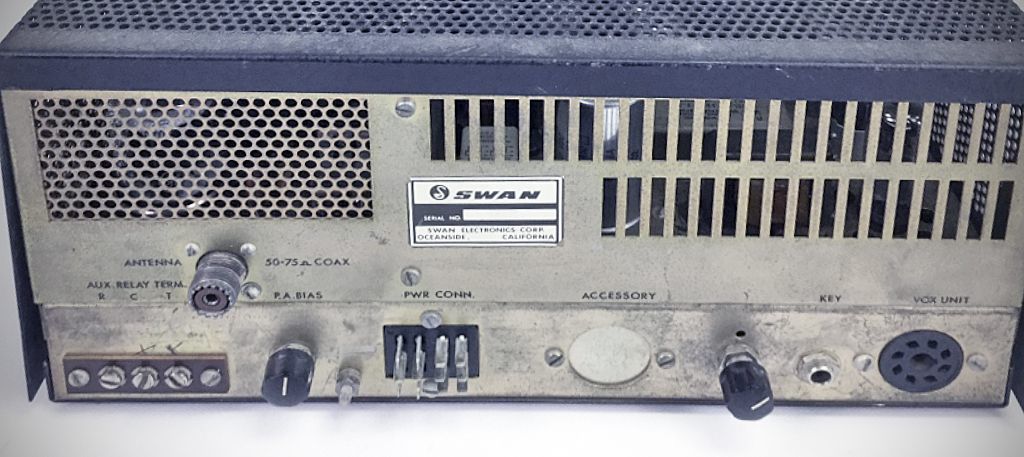
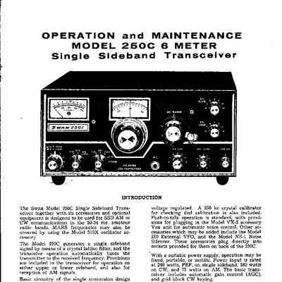
The Swan 250C introduces several key refinements and technical enhancements over the original Swan 250:
– Improved Receiver Front End: The 350C uses cascode-connected 6CW4 Nuvistors. Interestingly, while several sources note this change "significantly" improved the sensitivity and noise figure, the specifications in the 350 and 350C manuals are the same. See specification below.
– Adds a second RF amplifier (6CW4, V7)
– Enhanced VFO Stability: Features an upgraded 13.1 MHz solid-state VFO to improve frequency stability and minimize drift.
– Dial Accuracy & Tuning Controls: The megahertz control knob was recalibrated and fitted with a vernier drive.
– Adds a built-in 250 kHz crystal marker calibrator (and associated tube V18). Allows band coverage with dial readout accuracy within 2 kHz.
– Multi-Function Panel Meter: Now includes an S-meter function.
– Accessory Support & Wiring: Includes dedicated accessory sockets and pre-wired connections on the rear chassis for add-ons like the VX-2 VOX unit, Model 210C external VFO, Model 510X crystal oscillator, and Swan's mobile noise blanker/silencer.
Specifications
– Frequency Range: 50.0 to 54.0 MHz covered in 500 kHz segments.
– Operating Modes: SSB (Upper Sideband), AM (single sideband with carrier), and CW.
– Power Input:
SSB: 240 W PEP minimum (typically 280 W or higher on voice peaks).
CW: 180 W DC input.
AM: 75 W DC input.
– Receiver Sensitivity: Less than 0.5 uV for a 10 dB (S+N)/N ratio into a 50 ohm load.
– Noise Figure: Less than 3 dB.
– Selectivity: Bandwidth of 2.8 kHz at 6 dB down (10.698 MHz crystal lattice filter).
– Carrier Suppression: Greater than 50 dB.
– Unwanted Sideband Suppression: Greater than 40 dB.
– Spurious Radiation: Down more than 50 dB.
– Frequency Stability: Less than 100 Hz drift after warm-up; less than 100 Hz variation for a ±10% line voltage change.
– Audio Output: 4 W into a 3.2\ \Omega load.
– Output Impedance Matching: Pi-network matches 15 to 500 ohm resistive loads.
Power Requirements (External):
High Voltage: 800 VDC at 300 mA peak.
Medium Voltage: 275 VDC at 150 mA.
Bias Voltage: –110 VDC at 100 mA.
Filament Power: 12.6 VAC or DC at 5 A.
References
Bandswitching with the Drake TV-2. 73, Dec 1969, p. 26.