Note
QST, Oct 1969, p. 149. (270)
Ham Radio, Jun 1971, p 27. (270B)
QST, Feb 1971, p. 105. (Specifications)
QST, Oct 1972, p. 144.
QST, Jan 1973, p. 109.
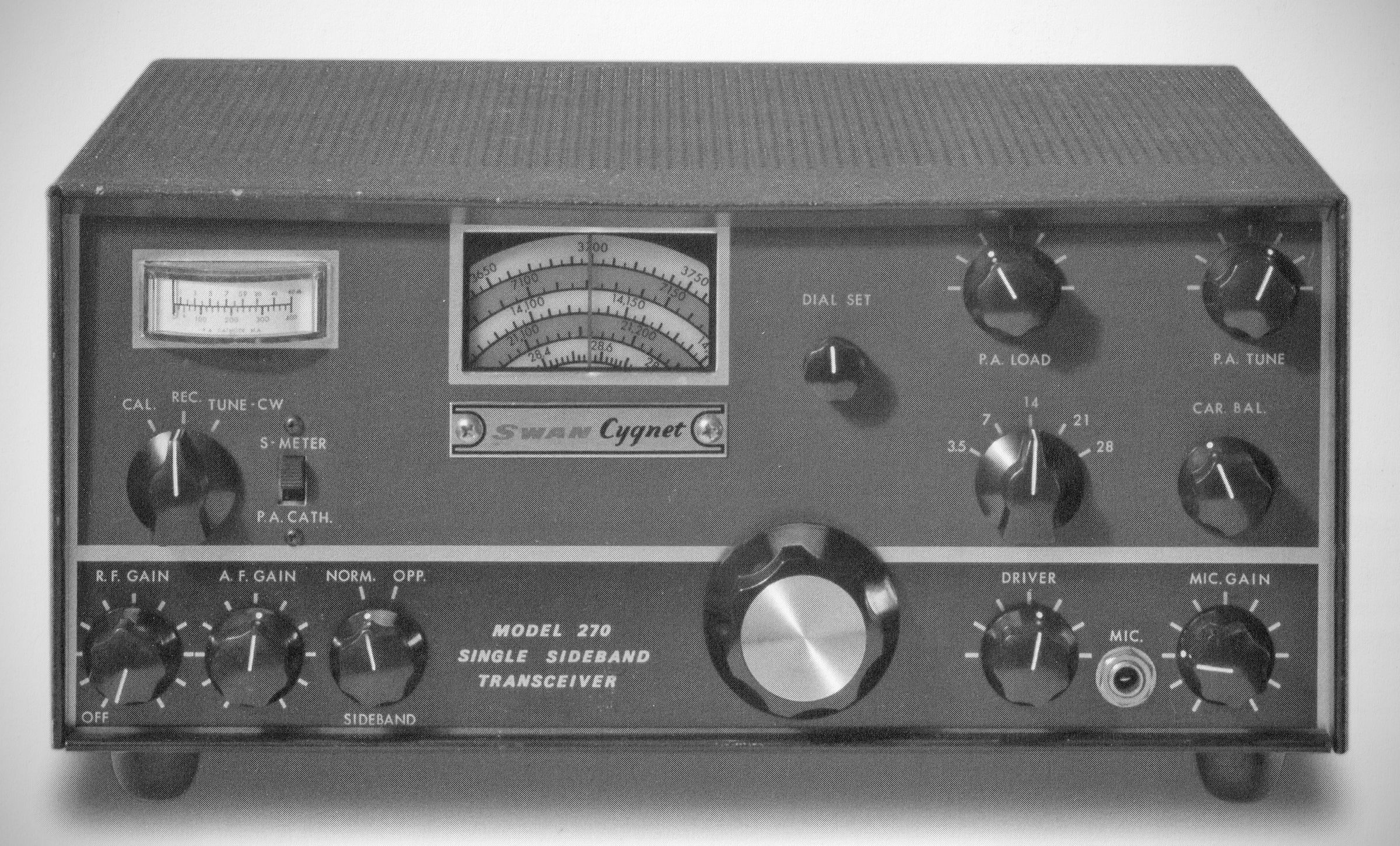
The Cygnet 270 was the same size and had the same power as the 260 that came before it, but added new features and performance. The 270 had an S-meter/transmitter tuning meter, selectable sidebands, an improved CF Networks filter, and separate RF and AF gain controls. It offered full coverage of the 80-10 meter bands and also retained the Cygnet 260 internal AC and DC power supplies.
The 260 and 270 were sold side by side through 1970. After 1970 the 260 appears to have been discontinued. (QST, Feb 1971, p.107.)
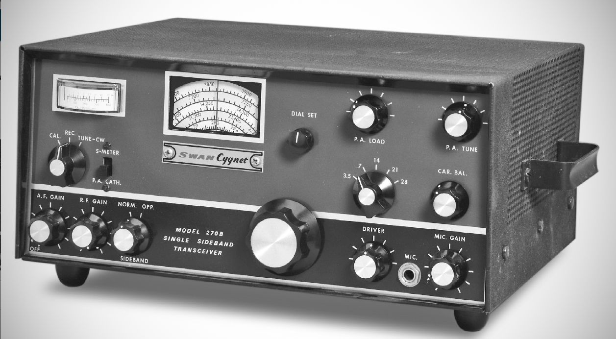
The model 270B was fundamentally the same as the 270. The most significant differences were the additional of a crystal lattice filter, and deletion of the built-in 12 volt DC power supply. Operation from 12 volts DC required the optional model 14-A plug-in converter.
Here are the complete specifications for the Swan Cygnet Model 270B transceiver as provided in page 2 of the manual:
Specifications
– Frequency Ranges
80 Meters: 3.5 to 4.0 Mc
40 Meters: 7.0 to 7.300 Mc
20 Meters: 14.0 to 14.350 Mc
15 Meters: 21.0 to 21.450 Mc
10 Meters: 28.0 to 29.7 Mc
– Power Input
Single Sideband, Suppressed Carrier: 260 watts PEP minimum on all bands
CW: 180 watts DC input on all bands
AM (Single Sideband with Carrier): 65 watts DC input on all bands
– Distortion: Distortion products down approx. 30 dB
– Unwanted Sideband Suppression: Down more than 50 dB
– Carrier Suppression: Greater than 50 dB
– Selectivity
Provided by 5500 Kc crystal lattice filter (270B only):
6 dB down: 2700 cycles wide
60 dB down: 4600 cycles wide
Shape Factor: 1.7
Ultimate Rejection: Greater than 100 dB
– Receiver Sensitivity: Better than 0.5 microvolt at 50 ohms impedance for Signal-plus-noise to noise ratio of 10 dB
– Audio Output: 3 watts to 3.2 ohm load. Response: Essentially flat from 300 to 3000 Hz in both receive and transmit
– Transmitter Output: 50 to 75 ohms
– Metering
Transmit: Power amplifier cathode current 0–400 mA
Receive: S-Meter 0–70 dB over S9
Tube Complement (14 total)
– V1 (12AU6): VFO Amplifier
– V2 (12BE6): Transmitter Mixer
– V3 (6GK6): Driver
– V4 (6LQ6): Power Amplifier
– V5 (6BZ6): Receiver RF Amplifier
– V6 (12BE6): Receiver Mixer
– V7 (12BA6): First I.F. Amplifier
– V8 (12BA6): Second I.F. Amplifier
– V9 (12AX7): Product Detector / Receive Audio
– V10 (6AV6): AGC Amplifier / Rectifier
– V11 (6AQ5): AF Output
– V12 (12BA6): 100 KC Calibrator
– V13 (6JH8): Balanced Modulator
– V14 (12AX7): Microphone Amplifier
Transistor Complement
– Q1 (2N706): Oscillator
– Q2 (2N5130): Buffer
– Q3 (2N706): Carrier Oscillator
– Q4, Q4 (model 270 only) 2N1522 power supply switching
Power Requirements
117 Vac: 60 cps at 4 amps
(208-220-240 Vac, 50–60 cps: at 2.5 amps max., export model)
270B
12–14 volts DC operation: with Model 14-A converter unit plugged into back of 270B:
Current drain: 8 amps
Receive mode: 12 amps average with voice modulation
TUNE mode: 25 amps maximum