Note
QST, Nov 1964, p. 103.
Allied Radio catalog 1966 (copyright 1965), p. 356.
QST, Jan 1966, p. 125.
QST, Jun 1966, p. 111. (specs and chart)
QST, Nov 1977, p. 117.
350B - intro date unknown, sold until 1979:
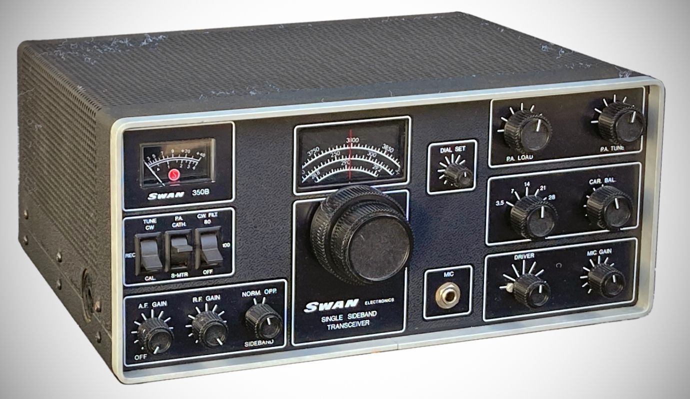
QST, Nov 1978, p. 193. (The 350D is the same as the 350B, but with digital display)
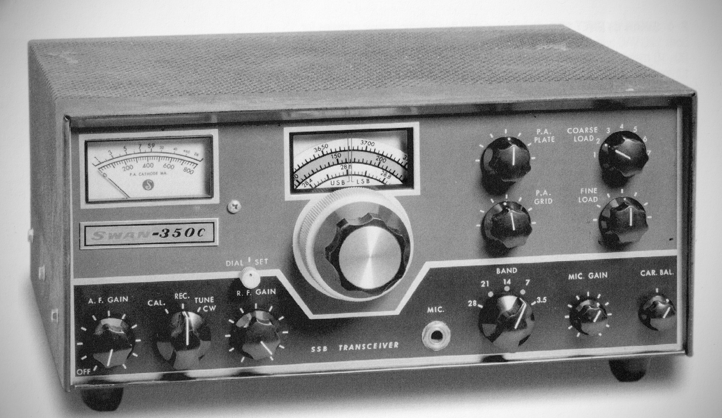
QST, Feb 1968, p. 115. (350C)
QST, Jun 1968, p. 109. (Discontinued in 1977)
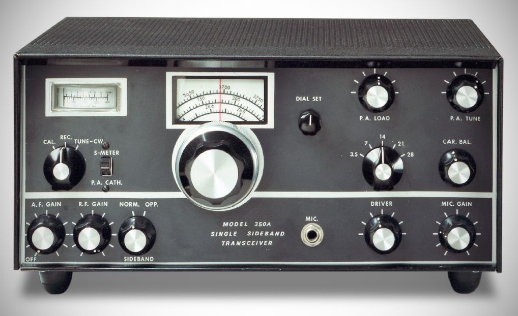
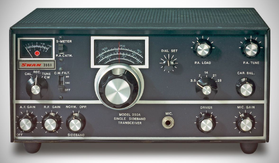
QST, Nov 1977, p. 117. (350D, digital display) (A and D sold concurrently)
350B and 350D close out: QST, Aug 1979, p.126.
This ad references "16 years of continuous production totaling 55,000 radios." Doesn't say whether this number includes just the 350 series, or all of the tube type rigs.
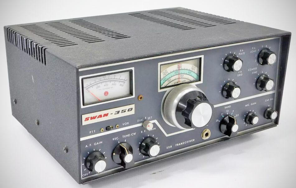
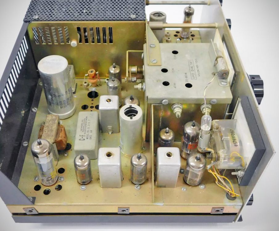
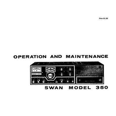
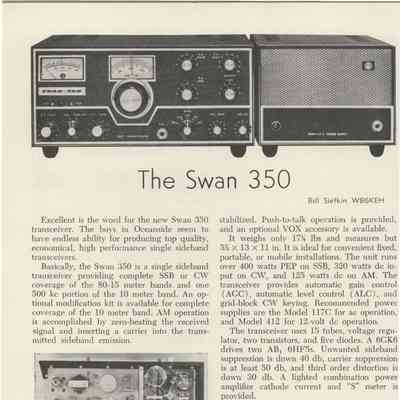
The Swan 350 made its debut in late 1964 and continued to evolve for another 15 years. The original 350 covered 80 through 10 meters, operating on the sideband customary for a particular band. A kit was available to enable sideband selection. SSB power input was 400 watts, with 320 watts on CW, and 125 watts on AM. The Swan 350's VFO was transistorized and the transceiver also used 16 tubes, including a pair of 6HF5 finals.
Here is the specifications list from page 2 formatted with standard sentence-case text:
Specifications (model 350)
– Power Input
SSB: 400 watts, PEP, minimum on all bands.
CW: 320 watts, DC input on all bands.
AM (Single Sideband with Carrier): 125 watts DC input on all bands.
– Distortion products down approximately 30 dB.
– Unwanted sideband down more than 40 dB.
– Carrier suppression greater than 50 dB.
– Sensitivity: Better than 0.5 uV at 50 ohms impedance for signal-plus-noise to noise ratio of 10 dB.
– Audio output, 4 watts to 3.2 ohm load. Response essentially flat from 300 to 3000 Hz in both receive and transmit.
– Transmitter Output: Wide-range Pi-network output matches antennas essentially resistive from 15 to 500 ohms impedance, with coarse and fine load adjustment.
Metering: Power amplifier cathode current 0–800 mA on transmit, S-Meter 0–70 dB over S9 on receive.
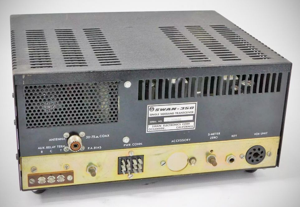
Rear Panel Controls and Connectors: Bias potentiometer, CW key jack, Jones plug power connector, Vox connector, Antenna jack, S-Meter zero, Auxiliary relay switchings.
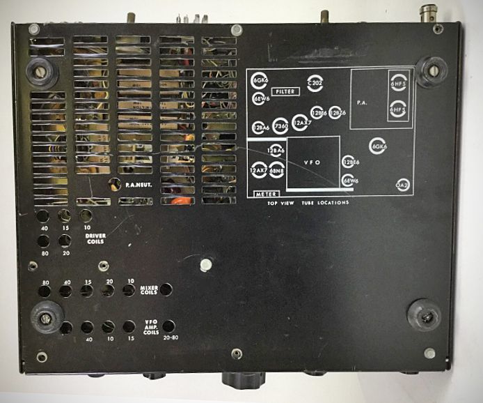
Tube Complement (16 total) (model 350)
– 6EW6 VFO amplifier
– 12BE6 transmitter mixer
– 6GK6 driver
– 6HF5 power amplifier
– 6HF5 power amplifier
– 12BZ6 receiver RF amplifier
– 12BE6 receiver mixer
– 6EW6 first IF amplifier
– 12BA6 second IF amplifier
– 12AX7 product detector / receive audio
– 6BN8 AGC amplifier / rectifier
– 6GK6 audio amplifier
– 7360 balanced modulator
– 12BA6 carrier oscillator
– 12AX7 mic. amplifier / transmit audio
– 0A2 voltage regulator
Diode and Transistor Complement (model 350)
– 2N706 oscillator
– 2N706 emitter follower
– TS-2 ALC diode
– TS-2 ALC diode
– TS-2 S-Meter delay diode
– 1N2974A Zener voltage regulator
– TS-2 relay silencing diode
Power Requirements
Filaments: 12.6 volts, 5.5 amps, AC or DC
Relay: 12 volts DC, 250 mA
Bias: –110 volts DC, 100 mA
Medium voltage: 275 volts DC, 150 mA
High voltage: 800 volts DC, 500 mA peak transmit
References
Review (350). QST, Sep 1965, p. 61.
Modifications. 73, Oct 1971, p. 101.