Note
QST, May 1964, p. 121.
QST, May 1965, p. 124.
QST, Jan 1966, p. 104.
CQ, Mar 1966, p. 37.
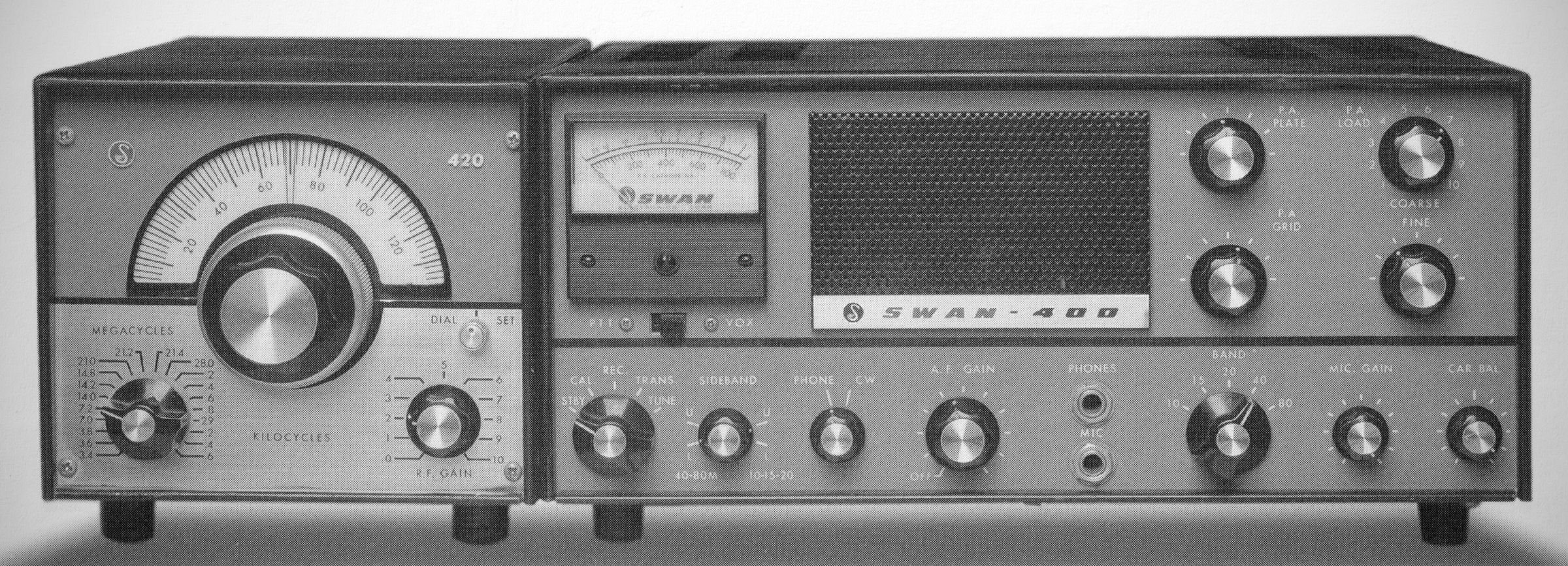
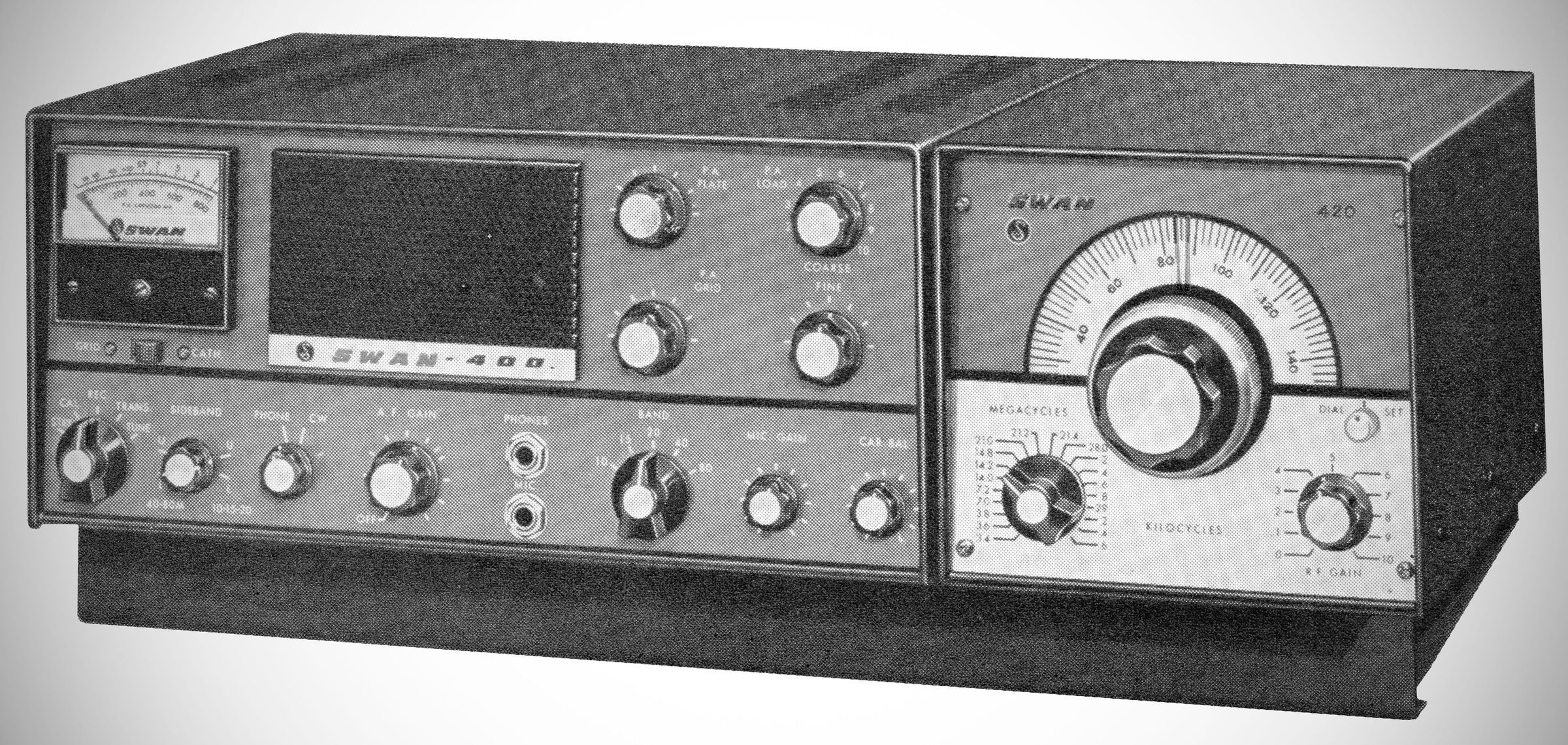
The Swan 400 transceiver had no internal VFO. It was designed to use the model 410 or 420 VFO, which provided complete coverage of the 80-10 bands, or the model 406 VFO, which covered the American phone portions of 80-15 meters and two 200 kHz segments of 10 meters. The Swan 400 was rated at 400 watts PEP on SS8, 320 watts on CW, and 125 watts on AM.
Features
– Operates with the Swan-406 or 420 Frequency Control Unit, and the Swan-117B, 117AC, or 512 DC Power Supply.
– Covers the 10, 15, 20, 40 and 80 meter bands.
– Two 6HF5 PA tubes, 6GK6 Driver Stage, 7360 balance modulator.
– Output Circuit: Wide range pi coupler, Coarse and Fine Adjustment.
– Grid Block CW Keying. Key jack on chassis rear.
– Transmitter metering: 0-800 ma. PA cathode., and grid current position for over-modulation indicator.
– Provision for plug-In VOX accessory.
– Overall audio bandpass: essentially flat from 300 to 3300 Hz, transmitting and receiving.
– Single Conversion Design. Spurious emission and image response down more than 80 db.
– Wide range AGC system. S-meter functions automatically when receiving.
– 100 KHz Crystal Calibrator.
– Built-In Speaker. Also provision for external speaker.
Specifications
– Frequency Coverage (Transceiver Base): Covers the 80, 40, 20, 15, and 10-meter bands.
– Modes of Operation: SSB (Single Sideband suppressed carrier), CW, and AM (Single Sideband with Carrier by zero-beating).
– Power Input:
SSB: 400 Watts PEP minimum on all bands.
CW: 320 Watts DC input on all bands.
AM: 125 Watts DC input on all bands.
– Receiver Sensitivity: Less than 0.5 microvolt at 50 ohms impedance for a signal-plus-noise to noise ratio of 10 dB.
– Suppression & Distortion:
Carrier Suppression: At least 50 dB.
Unwanted Sideband Suppression: At least 40 dB.
Distortion Products: Down at least 30 dB.
– Audio Output & Response: Approximately 3 watts to a 3.2-ohm load via built-in speaker; frequency response is essentially flat from 300 to 3000 cps on transmit and receive.
– Transmitter Output Impedance: Wide-range Pi-network matching resistive antenna loads from 20 to 300 ohms (with coarse and fine adjustments).
Tube Complement (17 total)
– 6EW6 VFO Amplifier
– 12BE6 Transmitter Mixer
– 6GK6 Driver
– 6HF5 Power Amplifier
– 6HF5 Power Amplifier
– 12BZ6 Receiver RF Amplifier
– 12BE6 Receiver Mixer
– 6EW6 First IF Amplifier
– 12BA6 Second IF Amplifier
– 12AX7 Product Detector / Receiver Audio
– 6BN8 AGC Amplifier / Detector
– 6GK6 Audio Output
– 12BA6 $100\text{ KC}$ Crystal Calibrator
– 7360 Balanced Modulator
– 12BA6 Carrier Oscillator
– 12AX7 Mic. Amplifier / Transmit Audio
– 0A2 Voltage Regulator
Power Requirements
Filaments: 12.6 volts 5.5 amps (AC or DC)
Relay: 12 VDC}, 250 mA
Bias: – 110 VDC, 100 mA
Medium Voltage: 275 VDC, 150 mA (transmit)
High Voltage: 800 VDC, 500 mA