Note
QST, Mar 1967, p. 125.
QST, Feb 1968, p. 115 (500C)
QST, Apr 1970, p. 137. (500CX)
QST, Feb 1971, pp. 102–103. (Specifications)
QST, Oct 1972, p. 144.
QST, Jul 1973, p. 146.
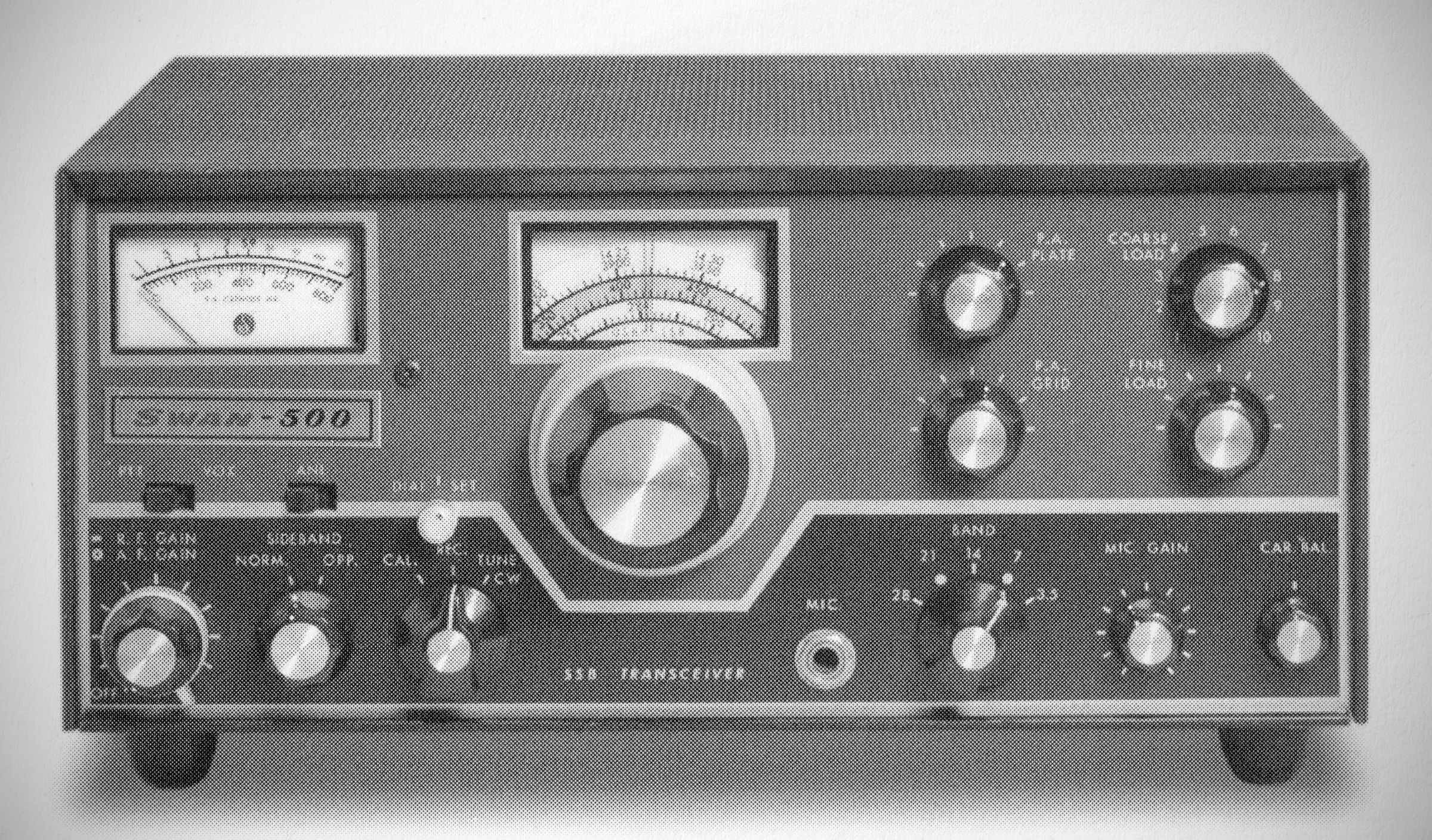
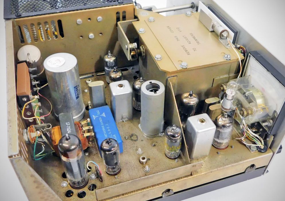
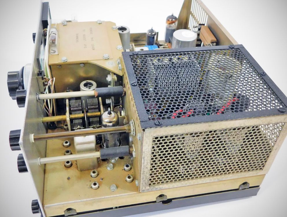
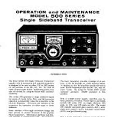
The 500 transceiver was the top of the Swan line when it was introduced in 1967. It offered selectable sidebands, a crystal calibrator, an automatic noise limiter, provision for an internal speaker, and a factory-installed socket for the 410 remote VFO. Power input was 480 watts PEP on SS8, 360 watts CW, and 125 watts AM. It also featured complete coverage of the 80-10 rneter bands.
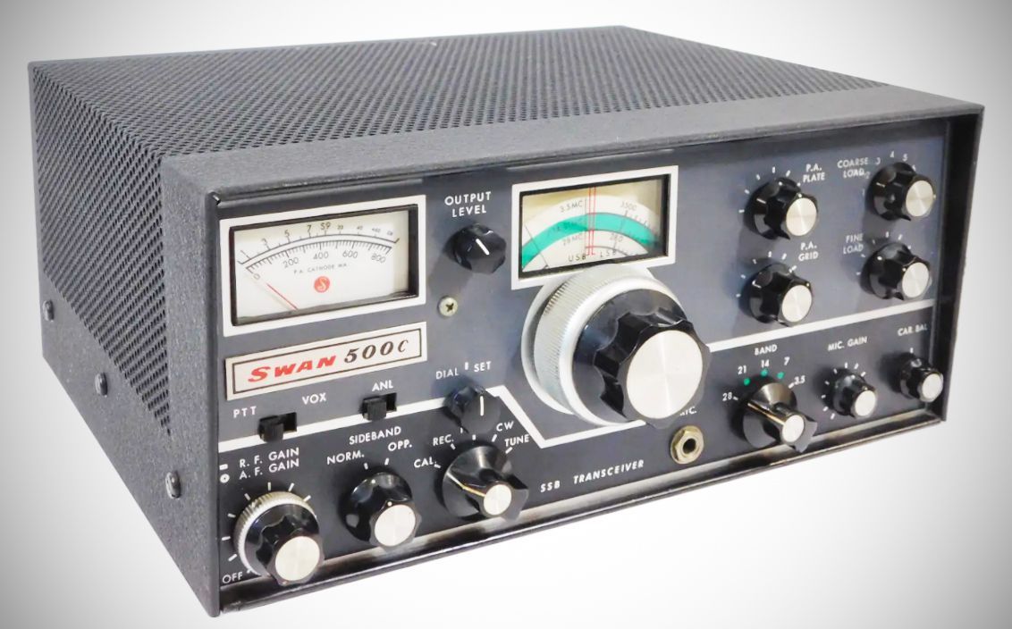
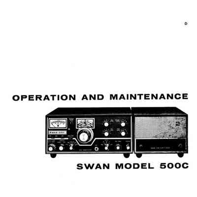
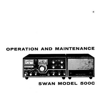
Swan 500C uses a pair of 6LQ6 tubes in its final, and was conservatively rated at 520 watts PEP. The transceiver used 17 tubes, 3 transistors, and 10 diodes. With the addition of Swan's VX-2 accessory, it had VOX operation on phone and semi-break-in on CW; $520.00.
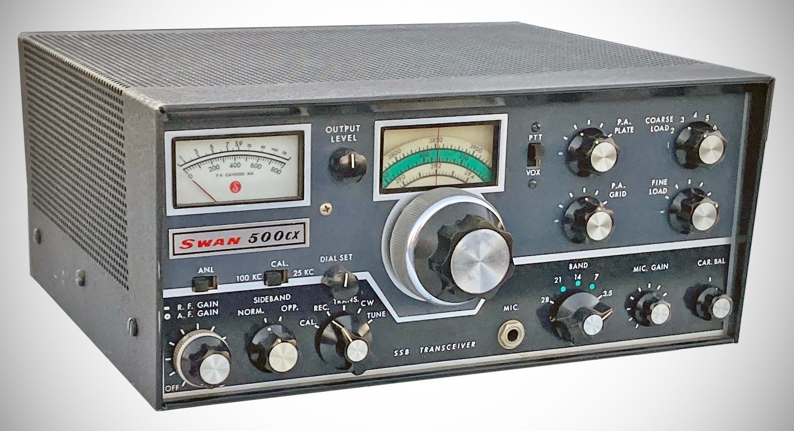
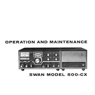
The Swan 500CX was a 550 watt, five-band transceiver. Its receiver was single conversion, but the 5.5 MHz IF prevented image problems. Changes from the 500C model included improved AGC and product-detector circuits, and a crystal calibrator with both 25 and 100 kHz markers. The optional SS-168 IF crystal filter was also available. $549.00.
Specifications
– Frequency Coverage
80 Meters: 3.5 to 4.0 MHz
40 Meters: 7.0 to 7.5 MHz
20 Meters: 13.85 to 14.350 MHz
15 Meters: 21.0 to 21.5 MHz
10 Meters: 28.0 to 29.7 MHz
(Note: MARS frequencies can be covered using the Model 405X crystal oscillator accessory.)
– Power Input
Single Sideband (PEP): 480 watts minimum on all bands.
CW (DC Input): 360 watts on all bands.
AM (DC Input): 125 watts on all bands.
– Distortion: Distortion products down approximately 30 dB.
– Unwanted Sideband Suppression: Down more than 50 dB.
– Carrier Suppression: Greater than 60 dB.
– Receiver Sensitivity: Less than 0.5 microvolt at 50 ohms impedance for a signal-plus-noise ratio of 10 dB.
– Audio Output: 4 watts to a 3.2 ohm load.
– Audio Frequency Response: Flat from 300 to 3000 cps in both transmit and receive.
– Output Matching: Wide-range Pi-network matches resistive antenna loads from 15 to 500 ohms with coarse and fine load controls.
– Metering:
Transmit: Power amplifier cathode current (0--800 mA).
Receive: S-Meter (0--70 dB over S9).
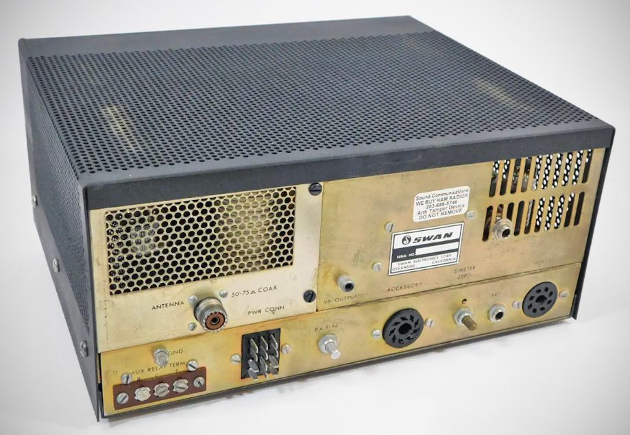
– Rear Panel Controls & Connections: Bias potentiometer, CW key jack, Jones plug power connector, Vox connector, Antenna jack, S-Meter zero, Auxiliary relay switching, Outboard VFO connector.
Tube Complement (model 350) (17 total)
– 6EW6 (VFO Amplifier)
– 12BE6 (Transmitter Mixer)
– 6GK6 (Driver)
– (2) 6HF5 (Power Amplifiers)
– 12BZ6 (Receiver RF Amplifier)
– 12BE6 (Receiver Mixer)
– 6EW6 (First IF Amplifier)
– 12BA6 (Second IF Amplifier)
– 12AX7 (Product Detector / Receive Audio)
– 6BN8 (AGC Amplifier / Rectifier)
– 6GK6 (Audio Amplifier)
– 7360 (Balanced Modulator)
– 12BA6 (Carrier Oscillator)
– 12AX7 (Mic. Amplifier / Transmit Audio)
– 0A2 (Voltage Regulator)
– 12BA6 (100 kHz Calibrator)
Semiconductor Complement (model 350)
– 2N706 (Oscillator)
– 2N706 (Emitter Follower)
– (2) TS-2 (ALC Diodes)
– 1N2974A (Zener Voltage Regulator)
– TS-2 (Relay Silencing Diode)
– TS-2 (AGC Charging Bypass)
Tube Complement (model 350C early and late) (16 total)
– 6EW6 (VFO Amplifier)
– 12BE6 (Transmitter Mixer)
– 6GK6 (Power Amplifier Driver)
– 6LQ6 (Power Amplifier)
– 6LQ6 (Power Amplifier)
– 12BZ6 (Receiver RF Amplifier)
– 12BE6 (Receiver Mixer)
– 6EW6 (First IF Amplifier)
– 12BA6 (Second IF Amplifier)
– 12AX7 (Product Detector / Receive Audio)
– 6BN8 (AGC Amplifier / Rectifier)
– 6GK6 (Audio Output Amplifier)
– 6JH8 (Balanced Modulator)
– V14: Carrier Oscillator (Note: Per the voltage chart and schematic, V14 is configured in the socket layout; the carrier oscillator function in some revisions incorporates transistor Q14)
– 12AX7 (Microphone Amplifier / Transmit Audio)
– 12BA6 (100 kHz Crystal Calibrator)
Semiconductors (model 350C early and late)
– 2N706 (VFO Oscillator)
– 2N706 (Emitter Follower)
– 2N706 (Carrier Oscillator)
– RCA 38679 (ALC Diode)
– RCA 38679 (ALC Diode)
– 1N34A (Relative Output Diode)
– 1N34A (Automatic Noise Limiter Diode)
– 1N34A (Automatic Noise Limiter Diode)
– RCA 38679 (CW Switching Diode)
– RCA 38679 (CW Switching Diode)
– 1N2974A (Zener Voltage Regulator)
– 750 mA / Relay Silencing Diode
– RCA 38679 (AGC Charging Bypass)
Tube Complement (model 350CX) (14 total)
– 6EW6 (VFO Amplifier)
–12BE6 (Transmitter Mixer)
– 6GK6 (Driver)
– 6LQ6 (Power Amplifier)
– 6LQ6 (Power Amplifier)
– 12BZ6 (Receiver RF Amplifier)
– 12BE6 (Receiver Mixer)
– 12BA6 (First IF Amplifier)
– 12BA6 (Second IF Amplifier)
– 12AX7 (Product Detector / Receive Audio)
– 6BN8 (AGC / ALC Amplifier)
– 6GK6 (Audio Amplifier / AF Output)
– 6JH8 (Balanced Modulator)
– 12AX7 (Microphone Amplifier / Transmit Audio)
Semiconductor Complement (model 350CX)
– 2N706 (VFO Oscillator)
– 2N706 (Emitter Follower)
– 2N706 (Carrier Oscillator)
– MPS 3693 (Crystal Calibrator)
– MPS 3693 (Crystal Calibrator)
– MPS 3693 (Crystal Calibrator)
– MPS 3693 (Crystal Calibrator)
– 1N34A (Relative Output Diode)
– 1N914 (Overload Diode)
– 1N34A (ANL Diode)
– 1N34A (ANL Diode)
– RCA 39804 / 1N3195 (CW Switching Diode)
– RCA 39804 / 1N3195 (CW Switching Diode)
– 1N2974A (Zener Regulator)
– RCA 39804 / 1N3195 (Relay Silencing Diode)
– 1N914 (AGC Diode)
– 1N914 (AGC Diode)
– 1N914 (AGC Diode)
Power requirements
Filaments: 12.6 V (5.5 A), AC or DC
Relay: 12 V DC (250 mA)
Bias: –110 V DC (100 mA)
Medium Voltage: 275 V DC (150 mA)
High Voltage: 800 V DC (500 mA Peak Transmit) (550 mA 350C and CX)
References
Review. CQ, Apr 1969, p. 50.