Note
QST, Dec 1963, p. 145. (available in January 1964)
QST, Jan 1964, p. 137.
QST, Apr 1964, p. 114.
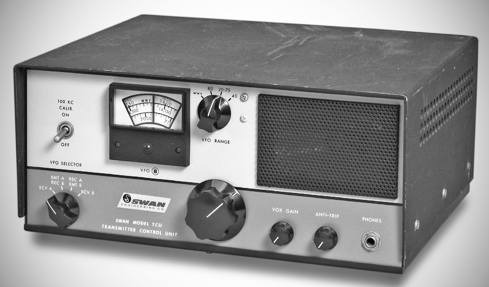
Designed as an outboard companion accessory to extend the capabilities of the Swan SW-240 single-sideband transceiver, the TCU matches the transceiver's cabinet dimensions and styling. The Swan TCU provided separate transmit and receive frequency control when used with the SW-240. In addition, it gave full coverage of the 80 meter CW band, allowed 15 MHz WWV reception, and incorporated VOX operation for the SW-240.
The TCU can also house the companion SW-117B AC power supply internally to keep the station footprint smaller.
⚠️ The TCU is not plug-and-play compatible with the SW-240. It requires a modification of the transceiver. All necessary parts to accomplish the modification were supplied with the TCU.
⚠️ The first SW-240 transceivers tuned from 3800 to 4000 KC. If 80 meter CW is desired, it may be found that the exciter tune control will not adjust to full CW power at the lower end of the 80 meter CW band. This condition is not indicative of any defect in either the transceiever or TCU, and would constitute a problem only if you wish to transmit at the low end of the 80 meter band. It will be necessary then to change and realign two tuned circuits.
Features
– Independent VFO Control (Split/Non-Transceive Operation):
Provides a separate VFO to enable split-frequency operation (transmitting on frequency A while receiving on frequency B, or vice versa). Control is managed via grid-bias switching between the transceiver's internal VFO and the TCU's VFO.
– Expanded Frequency Coverage:
In addition to the standard bands, the TCU extends coverage across the 80-meter CW segment (3500 – 3650 kHz) and includes a fixed setting for receiving WWV/WWVH time signals on 15 MHz
WWV: 15 MC
80 M CW: 3,500 to 3,650 KC
75 M: 3,650 to 4,000 KC
40 M: 7,000 to 7,300 KC
20 M: 14,000 to 14,350 KC
– Voice Operated Transmission (VOX):
Incorporates a full tube-driven VOX circuit (using a 6BN8 and 12AT7 layout). Controls include front-panel VOX Gain and Anti-Trip adjustments, allowing hands-free T/R switching directly from the microphone audio signal without cycling a manual PTT switch.
– Integrated 100 kHz Crystal Calibrator:
Features a built-in 12AU6 crystal oscillator stage with a front-panel toggle switch for precise dial calibration checks.
– Audio Output:
Houses an internal 3 x 5" oval speaker and a front-panel headphone jack.
Front Panel:
Top Section: Analog main tuning dial, 4-position VFO Range switch (WWV, 80M CW, 20–75M, 40M), Calibrate ON/OFF toggle, and speaker grille.
Bottom Section: 4-position VFO Selector knob (Transceive A, Transmit A / Receive B, Receive A / Transmit B, Transceive B), Main Tuning knob, VOX Gain pot, Anti-Trip pot, and a 1/4-inch Phone jack.
Tube Lineup
– 6BH8: VFO / Cathode Follower located inside the TCU VFO compartment
– 6BN8: VOX Amplifier & Anti-Trip Diode Rectifier
– 12AT7: VOX Audio Amplifier & Relay Control Tube
– 12AU6: 100 KC Crystal Calibrator Oscillator
– 12AV6: VFO Coupling Tube part of the modification kit, mounted directly on the SW-240 transceiver chassis
Interconnection & Power:
Powered via a 12-conductor cable routed from the modified SW-240 transceiver.
Requires a simple wiring harness modification on the SW-240 chassis, adding a 12-pin rear connector, an auxiliary 12AV6 VFO coupling tube, and an RF phono jack.