Note
QST, Jun 1968, p. 117.
QST, Feb 1971, p. 107. (TV-2B, probably earlier)
QST, Sep 1972, p. 115. (TV-2C, probably earlier)
QST, Jan 1973, p. 109.
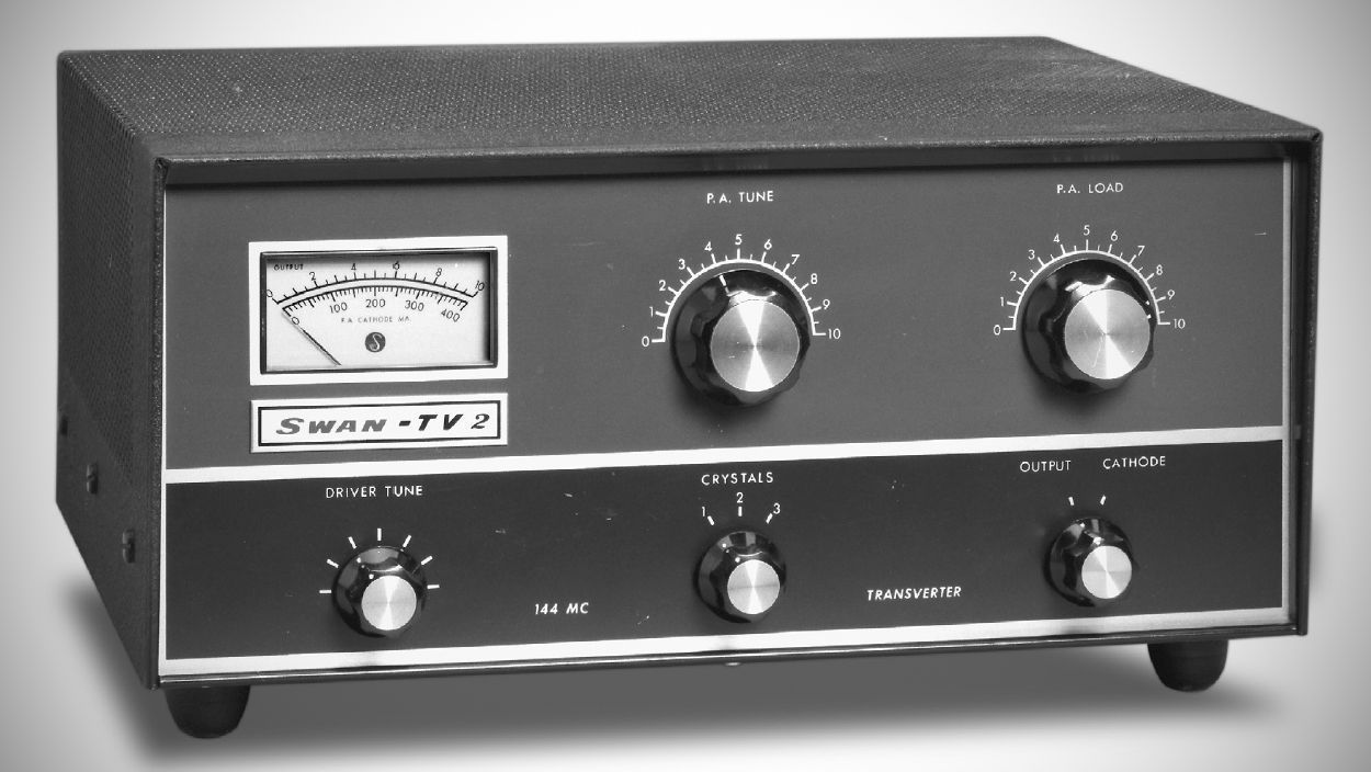
Swan’s TV-2 two meter transverter used a 14 MHz IF. Its frequency coverage on 2 meters was proportional to the transceiver’s tuning range on 20. A front panel switch selected heterodyne crystals for three 2 meter band segments. The TV-2 could be ordered with a 50 MHz IF for use with the Swan 250, 250C, 350, 350C, 400, 500, 500C, and 500CX. The 5894B final was rated at 240, 180, and 75 watts input on SSB, CW, and AM, respectively.
The TV-2 converts HF/VHF signals to and from the 2-meter band, using standard intermediate frequencies (IF)—most commonly 20 meters, though 15, 10, or 6 meters were available options. The unit utilizes solid-state circuitry (FETs and bipolar transistors) for the receiving converter and crystal oscillator stages, alongside a vacuum tube power amplifier and driver section for high-power transmission.
The differences between the three versions are the increased use of solid state to replace tubes. In the "B" version the crystal oscillator and tripler were replaced with transistors, and in the "C" version the receiver mixer was replaced with a transistors and the nuvistors were replaced with FETs.
Features
– Metering: P.A. Cathode Current (0–400 mA) and Relative Output (0–10)
– Panel Controls: P.A. Tune, P.A. Load, Driver Tune, Crystal Selector, Meter Switch, 144 MHz Transverter On-Off
– Rear Controls & Connectors: P.A. Bias Adjust, Power Supply Connector, Relay Control Jack, I.F. Output Jack, Coaxial Antenna Connector, Low Frequency Antenna Jack
Specifications
– Output Frequency Range: 144–148 MHz (2-meter band)
– Input (IF) Range: 20-meter band (Standard); 15-meter, 10-meter, or 6-meter bands (Optional)
– Crystal Selection: 3-position crystal selector switch for covering multiple band segments
– Transmitter Power Rating:
SSB Voice: 240 Watts P.E.P. input
CW: 180 Watts input
AM: 75 Watts input
TUNE Mode Output: 80 to 100+ watts power output
– Output Impedance: 50 to 75 Omega coaxial cable, series-tuned link coupling
– Distortion Products: Approximately 30 dB below rated output
– Receiver Front-End: 3 x RCA 40673 FETs
– Noise Figure: Less than 3 dB
Tube Lineup ("B" version)
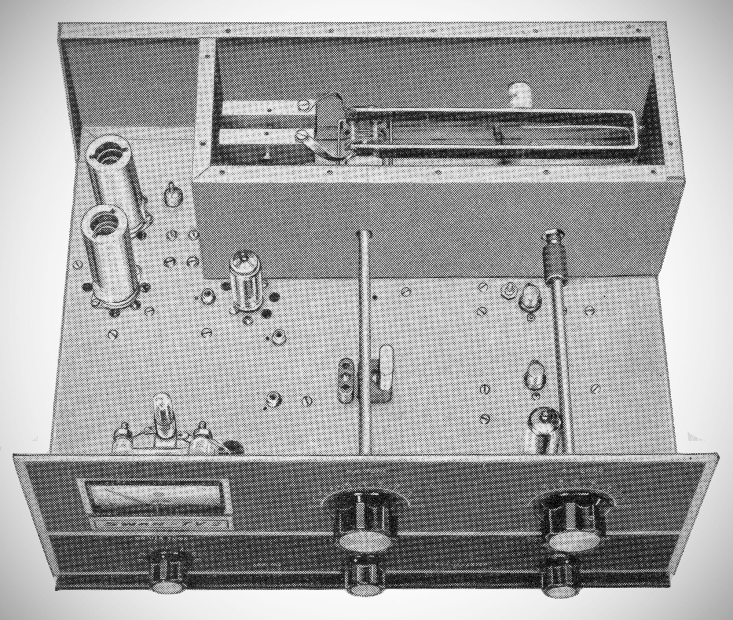
V1 6JK6 Injection Amplifier
V2 12BY7 Transmit Mixer
V3 5763 Driver
V4 5894B / 8737: Power Amplifier
V5 6CW4 1st RF Amplifier
V6 6CW4 2nd RF Amplfier
V7 6HA5 Receiver Mixer
Tune Lineup ("C" version)
V1 6JK6 Injection Amp
V2 12BY7 Transmit Mixer
V3 6360 Driver
V4 5894B / 8737: Power Amplifier
Transistors:
– Rec. R.F. Cascade: RCA 40673 FETs (2)
– Rec. Mixer: RCA 40673 FET (1)
– Crystal Oscillator & Multiplier: 2N706 (2)
Power Requirements
(Normally supplied via an external Swan 117XC power supply shared with the transceiver):
– Filaments: 12.6 V AC or DC @ 2.04 A
– Medium Voltage: +275 V DC @ 120 mA
– High Voltage: +800 V DC @ 240 mA
– Bias Voltage: –110 V DC @ 6.4 mA
– Oscillator Supply: –10 V DC regulated @ 9 mA
– Relay Supply: +12 V DC @ 125 mA