Note
QST, May 1946, pp. 112–113.
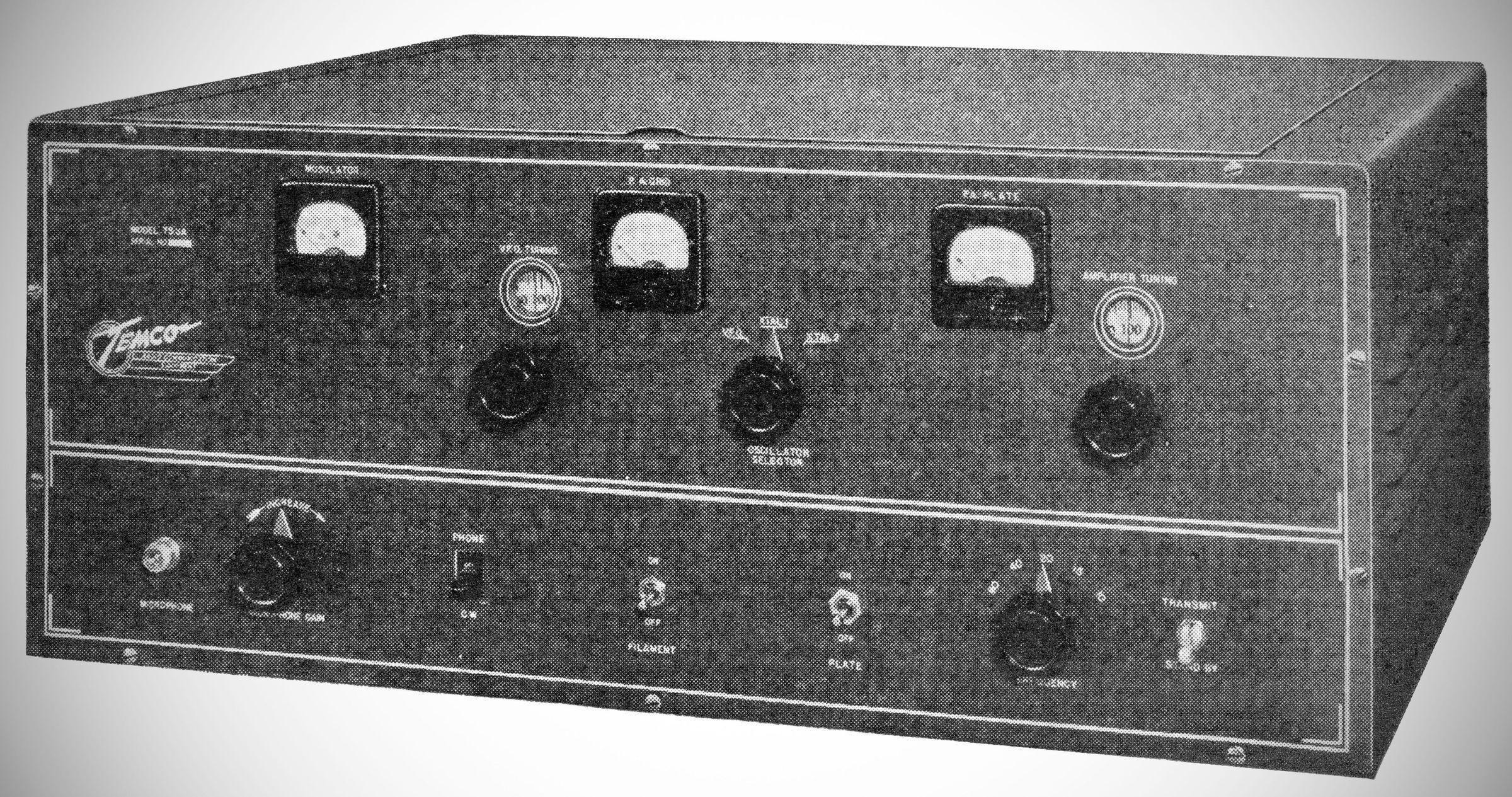
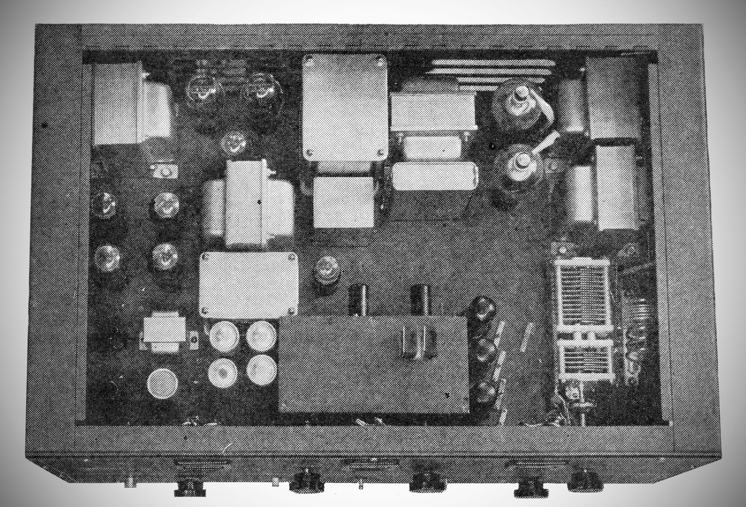
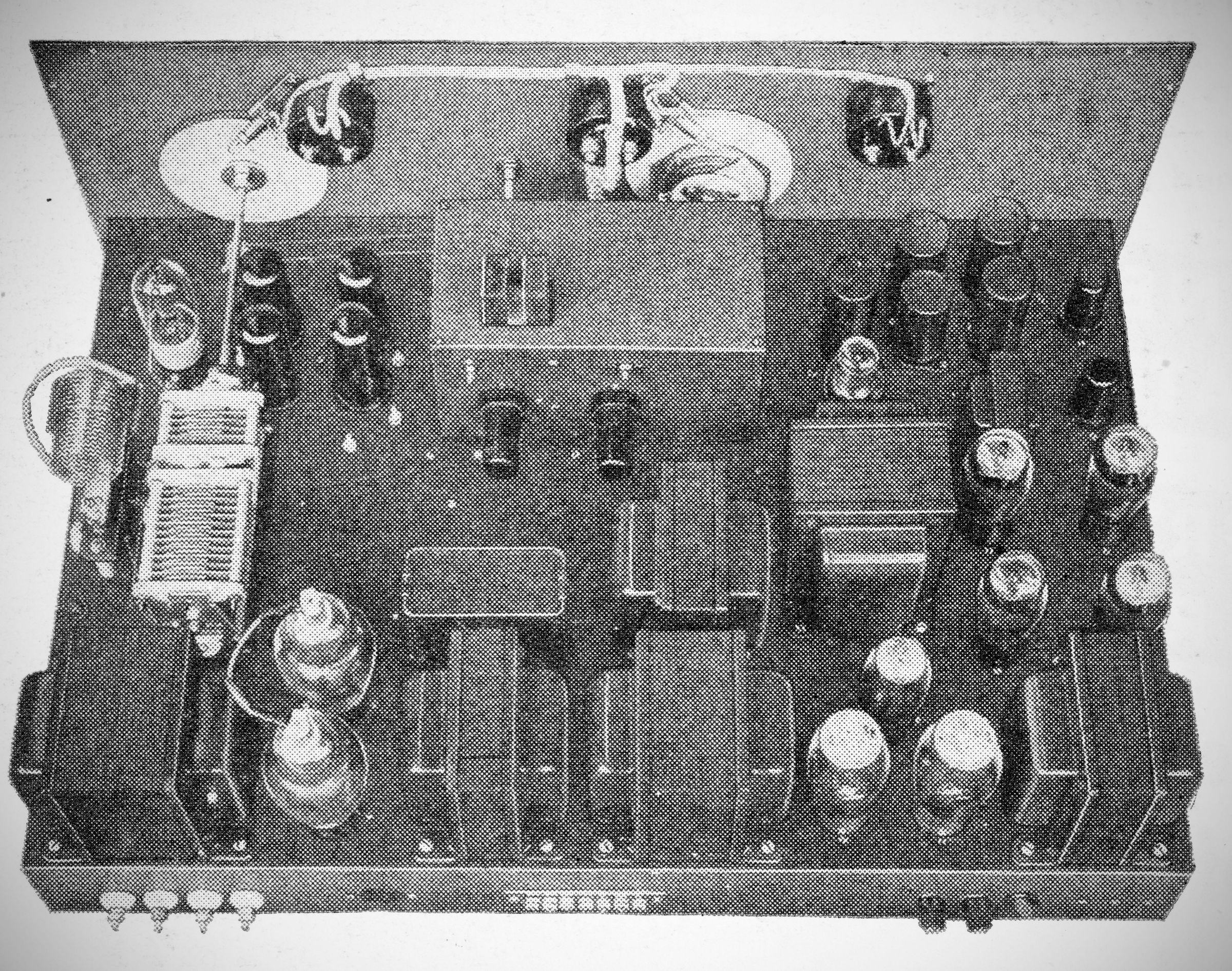
The TEMCO Model 75-GA is a table-top AM/CW transmitter. It features a band-switching exciter, a speech amplifier, a modulator, and three built-in power supplies all "compactly" arranged on a single horizontal chassis. (The unit is 30" wide and 21" deep, and weighs 140 pounds.)
Features
The unit features two methods of frequency control: a temperature-compensated Variable Frequency Oscillator (VFO) (tunable from 3500 to 4000 KC) and an untuned crystal oscillator with dual crystal holder provisions.
Band switching is handled directly from the front panel. Returning to a pre-set frequency requires only setting the band switch, inserting the correct final amplifier plug-in coil, and adjusting the pre-logged dial positions.
To address the extreme width of the 28 megacycle band, the 28 MC multiplier stage uses a variable tuning slug driven by the VFO tuning dial to ensure proper, constant grid drive across the entire band.
Modulation: High-level Class AB_2 modulation with 100% capability. A dedicated front-panel switch (S_7) short-circuits the secondary of the modulation transformer during CW operation to prevent hazardous transient voltages.
Flexible Output Coupling: Each final amplifier plug-in coil features a fixed, tapped coupling link. Using a flexible lead and clip, operators can adjust the active turns to match untuned transmission lines (balanced or unbalanced) between 30 and 600 ohms directly.
Metering: Built-in front-panel meters monitor modulator plate current, final amplifier grid current, and final amplifier plate current.
Safety Interlocks: Equipped with an electrical cabinet safety interlock switch that automatically cuts off the high-voltage supply when the top cover is opened.
Specifications (For 75-GA)
– Emission Types A-1 (CW Telegraphy) and A-3 (AM Telephony)
– Power Output 100 Watts on A-1 (CW); 75 Watts on A-3 (AM)
Up to 125W on CW and 95W on Phone under optimal conditions on lower bands)
– Frequency Ranges
3.5 to 4.0 MHz
7.0 to 7.3 MHz
14.0 to 14.44 MHz
21.0 to 21.5 MHz
28.0 to 29.7 MHz
– Audio Frequency Response ±2 dB from 100 to 6,000 Hz
_ Audio Distortion Less than 8% at 85% modulation
– Noise Level –45 dB or better below 100% modulation
– Input Level (Microphone) Approx.–55 dB (from high-impedance crystal or dynamic mic)
– Keying Speed 50 words per minute or better
Power Source 110–120 Volts, 50/60text{ Hz} AC |
Power Requirements
Standby (filaments only): 90 Watts
CW (key up): 185 Watts
CW (key down): 340 Watts
AM (zero mod): 490 Watts
AM (100% mod average): 520 Watts
– Power Factor Approximately 90%
Tube Complement
The transmitter utilizes a total of 18 vacuum tubes. The official tube lineup and their individual functions are detailed below:
Radio Frequency (RF) Section
(1) 6J5 (V1): Variable Frequency Oscillator
(1) 6AG7 (V2): Class A Buffer and untuned Crystal Oscillator
(4) 6L6 (V3, V4, V5, V6): Frequency Multipliers / Doublers
V3: 3.5 MC amplifier / 7 MC doubler
V4: 14 MC doubler
V5: 21 MC tripler
V6: 28 MC doubler
(1) TB35 (V7): Final Class C Power Amplifier
(1) VR150 (V8): Oscillator Voltage Regulator
Audio (Speech Amplifier & Modulator) Section
(1) 6SJ7 (V10): Input Voltage Preamplifier
(1) 6J5 (V11): Modulator Driver
(4) 6L6G (V12, V13, V14, V15): Class AB_2 Modulators (Push-Pull Parallel)
Power Supply Rectifiers
(1) 5R4GY (V9): Exciter Plate Supply Rectifier
(1) 5R4GY (V16): Speech Amplifier / Modulator Screen Plate Supply Rectifier
(1) 5R4GY (V17): Modulator Plate Supply Rectifier
(21) 866A (V18, V19): Power Amplifier Plate Supply Rectifiers (Half-wave mercury vapor)