Note
QST, Dec 1963, p. 7. "soon to be in production."
QST, Sep 1964, p. 7.
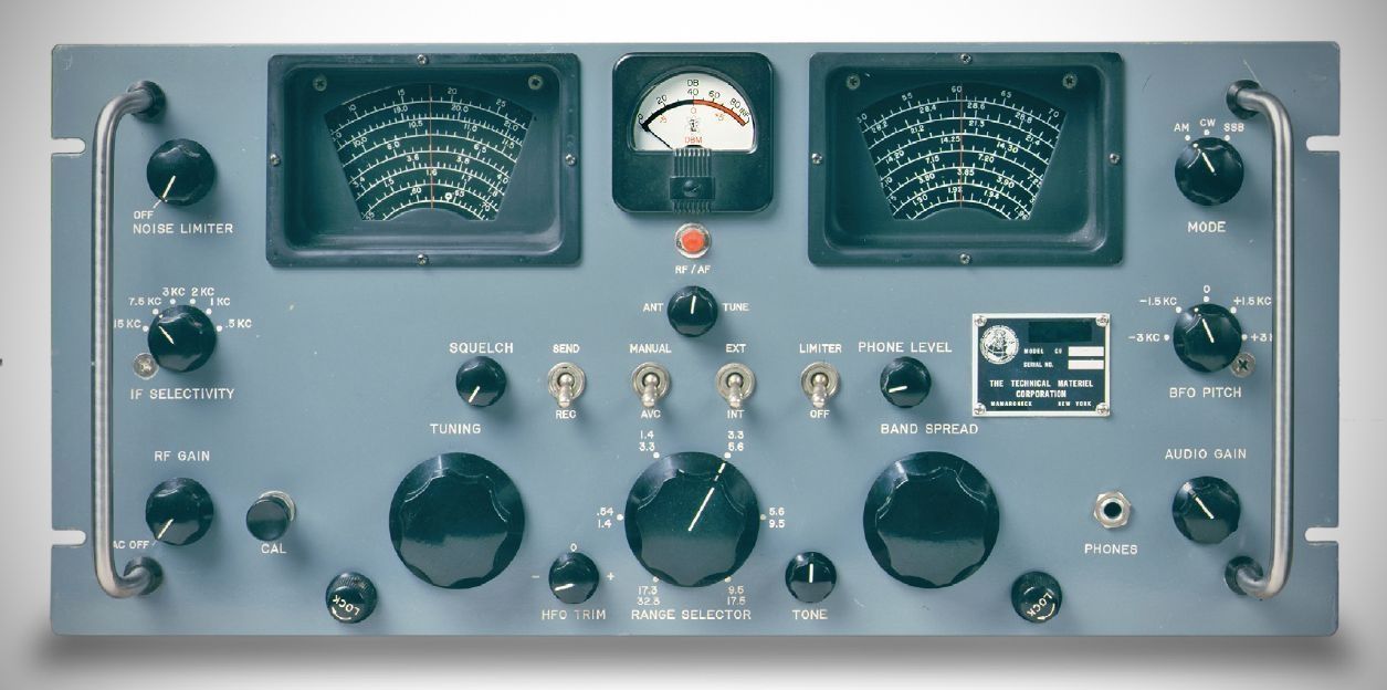
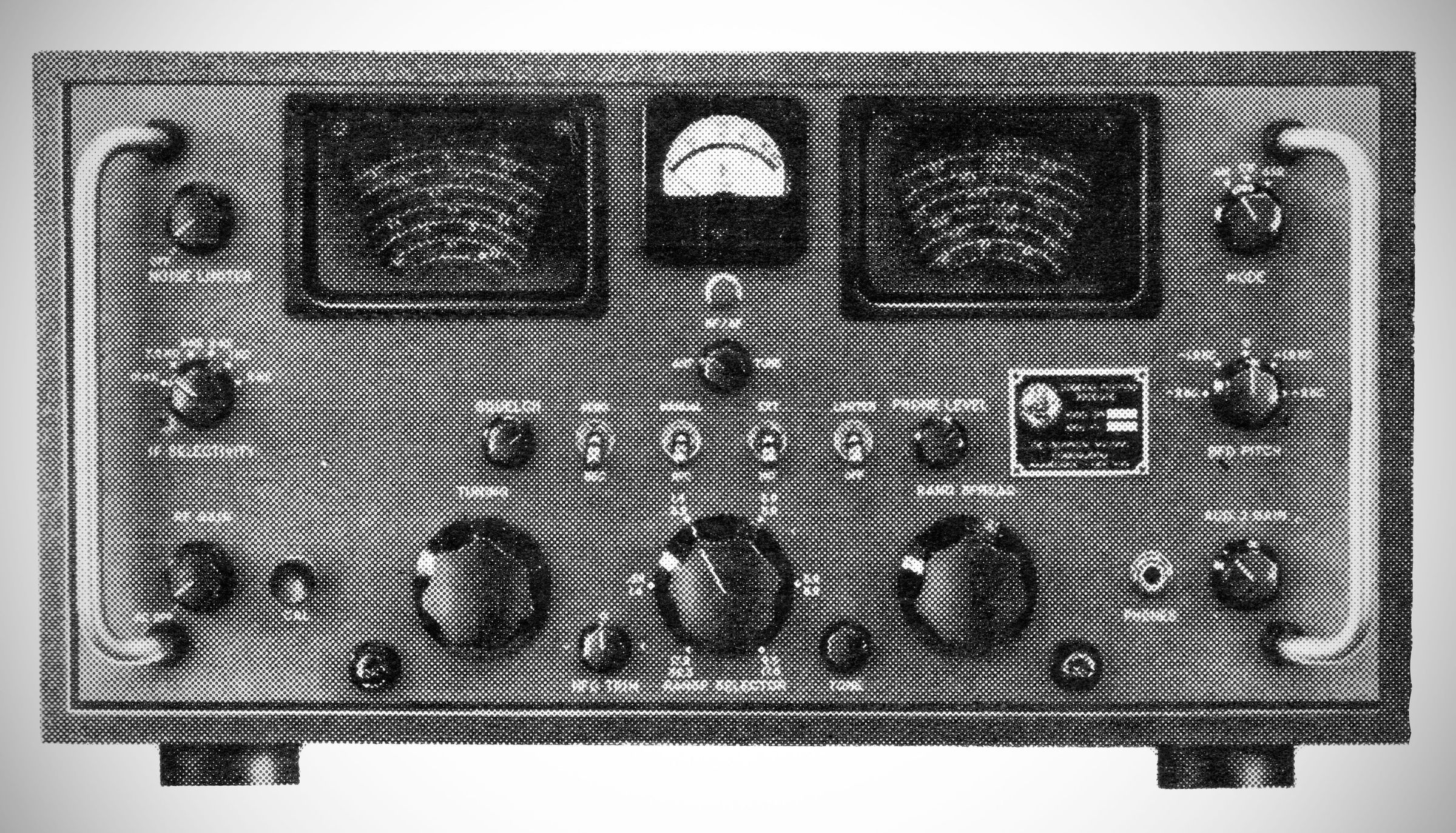
The Technical Materiel Corporation produced scarcely more than 100 examples of the GPR-92 receiver. The 18-tube set covered 0.54–32 MHz in five bands. The receiver shown here has amateur band calibration on the band-spread dial. Other versions were made with commercial or broadcast-band spread.
Frequency Coverage:
Band 1: 0.54 to 1.4 MHz
Band 2: 1.4 to 3.3 MHz
Band 3: 3.3 to 5.6 MHz
Band 4: 5.6 to 9.5 MHz
Band 5: 9.5 to 17.5 MHz
Band 6: 17.3 to 32.3 MHz
The unit can be used as a standalone communications receiver or integrated into a larger communications system for diversity reception, for example.
Modes: AM, Compatible AM (AM equivalent), CW, MCW, SSB
With additional equipment, it can also receive: IISB, FSK, and FAX.
Features
– Selectivity: Six selectable IF bandpass values (15 kHz, 7.5 kHz, 3 kHz, 2 kHz, 1 kHz, and 0.5 kHz) allow optimal tuning for different signal types.
– Double Conversion: Uses double i-f frequency conversion (converting from 3955 kHz down to 455 kHz) on the three highest tuning bands (Bands 4, 5, and 6) to maintain a high image rejection ratio. Single conversion to 455 kHz is used on Bands 1, 2, and 3.
– Calibration & Tuning: Electrical bandspreading is provided on Bands 2 through 6 (all except the broadcast band). An internal crystal-controlled oscillator generates calibration markers at 100 kHz intervals across the entire spectrum.
– Noise & Squelch Control: Includes separate RF and audio noise limiters, separate RF and audio volume controls with AVC, and an adjustable squelch circuit with an external alarm output when squelched.
– Muting & System Provision: Features a REC MUTE input for automatic receiver muting when paired with a transmitter, as well as provisions/isolation amplifiers for external high-frequency and BFO oscillators.
– Audio & Auxiliary Outputs: Produces IF, AVC, and DIODE LOAD outputs. Audio outputs include speaker outputs for 4, 8, or 16 ohms; a 600-ohm balanced line output; and a front-panel headphone output with a dedicated PHONE LEVEL control.
Specifications
– Hum Level: More than 50 db below rated output.
– Image Ratio: 80 db average throughout the frequency range.
– IF Rejection: At least 80 db throughout the frequency range.
– Intermodulation: At least 70 db down.
– AVC: An 80 db rise in input signal from 1 microvolt produces less than a 2 db change in audio output.
– Audio Response: Flat within 1.5 db from 200 to 8500 cps.
– Antenna Input: 72 ohms unbalanced.
– IF Output: At least 10 millivolts rms into 50 ohms via BNC connectors.
– Operating Temperature: 0°C (32°F) to 50°C (122°F).
Vacuum Tubes (18 total)
– OB2: Voltage regulator
– 6CB6A: 100 KHz Marker oscillator
– 6DC6: 1st RF amplifier
– 6BA6: 2nd RF amplifier
– 6EW6: HFO isolation amplifier
– 6BA7: 1st mixer
– 6AU6A: High frequency oscillator HFO
– 6AU6A: IFO isolation amplifier
– 6U8A: Combination 2nd mixer, 1st I-F amplifier, and I-F oscillator
– 6BA6: 2nd I-F amplifier
– 6AL5: RF noise limiter
– 6AZ8: Combination 3rd I-F amplifier and squelch amplifier
– 6U8A: Combination I-F output isolation amplifier, AVC amplifier, and AVC detector
– 6BA6: 4th I-F amplifier
– 12AT7: Combination product detector and beat frequency oscillator BFO
– 6AB4: Isolation amplifier for external BFO
– 12AX7A: Combination meter amplifier and audio driver
– 6AQ5A: Audio output amplifier
Diodes & Rectifiers
CR101 through CR104 (1N1084): Power rectifiers
CR105 (1N34A): AM detector
CR106 (1N463): Audio noise limiter
CR107 (1N34A): Meter rectifier
Primary Power: 115 ±10 VAC or 230 ±20 VAC, 50 to 400 Hz, 125 watts.