Note
QST, Nov 1963, p. 7
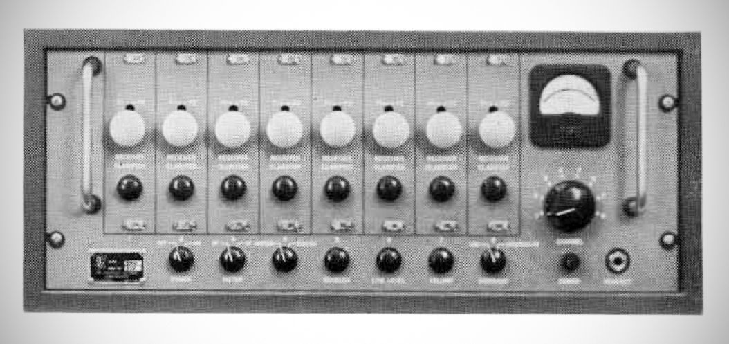
The TMC SMR-1 is a completely solid-state superheterodyne communications receiver introduced in 1963.
Frequency Range & Tuning: Operates across 2 to 32 MHz divided into four bands. It utilizes fixed-tuned, crystal-controlled plug-in modules (Model TTRR-1 through TTRR-4) to select up to eight distinct channels. Each TTRR module features two selectable local oscillator frequencies allowing operation on two separate frequencies within the module's bandwidth without requiring realignment.
Modes of Reception: Receives single sideband (upper or lower), amplitude modulation equivalent (AME), continuous wave (CW), modulated continuous wave (MCW), facsimile (FAX), and frequency shift keying (FSK). It can also tune single-sideband components of standard AM or independent sideband (ISB) transmissions.
The SMR-1 employs double conversion (converting the r-f signal down to a first IF of 1.75 MHz, and then to a second IF of 250 kHz) to maintain high image rejection (a minimum of 50 dB from 2 to 28 MHz). Selectivity is provided by a sharp 250 kc crystal bandpass filter (2.75 kHz bandwidth).
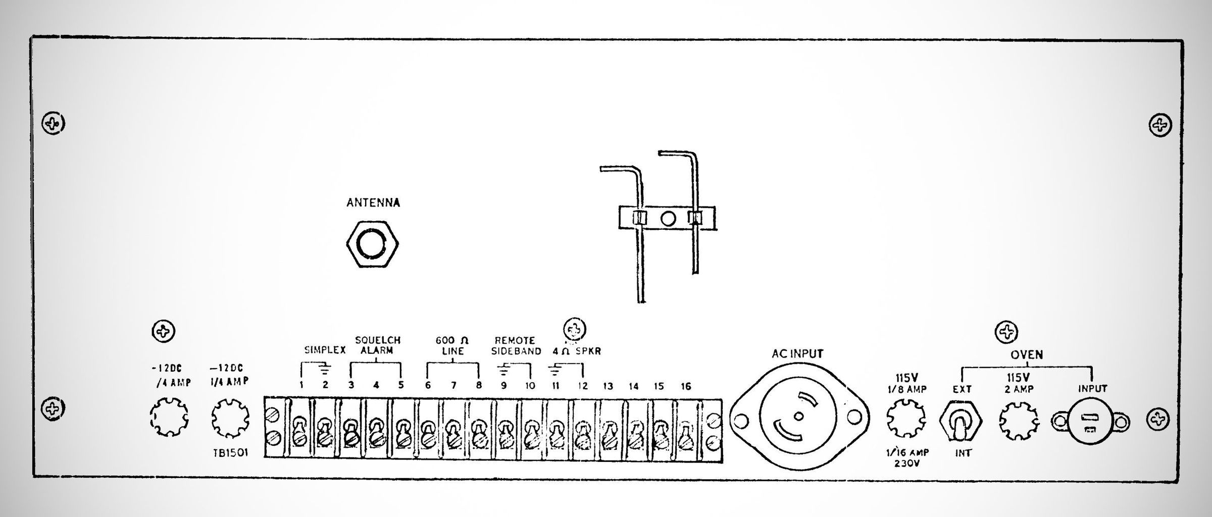
Audio Outputs: Provides two discrete audio outputs: a 500 milliwatt output into 4 ohms (for an internal/external speaker or front-panel headphone jack) and a 1 milliwatt balanced output into 600 ohms with an independent line level control.
ncludes local or remote sideband selection, an adjustable squelch circuit with external alarm dry contacts, built-in panel metering for RF/AF levels, and low overall power consumption.
Designed for mounting in a standard 19-inch equipment rack (7 inches high, 16 inches deep) or a tabletop cabinet, weighing 50 pounds rack-mounted or 70 pounds in a cabinet.
Variant (Model SMRA-1)
TMC also produced the SMRA-1 variant, which replaces the manual front-panel channel switch with an automated rotary switch-solenoid and an added rear control connector. This modification allows the receiver to act as a slave stepping switch for fully remote channel selection.
Here are the specifications transcribed directly from Section 1-3 of the manual:
Specifications
– Frequency range: 2 to 32 MHz divided into four bands using the following TTRR modules:
Band 1: 2–4 MHz, TTRR-1
Band 2: 4–8 MHz, TTRR-2
Band 3: 8–16 MHz, TTRR-3
Band 4: 16–32 MHz, TTRR-4
– Number of channels: 8 (each having a separate TTRR module).
– Tuning System: Each TTRR module is fixed-tuned to a particular frequency within its band. The receiver is tuned by selecting one of the different modules (channels).
– Frequency control: Crystal-controlled oscillators are used throughout the receiver.
– Types of reception: AME, CW, FAX, FSK, MCW, and SSB (upper or lower). AM and ISB signals can also be received, but this feature is generally not used.
– Sensitivity: 1 uV input for 15-db signal-plus-noise to noise ratio.
– Audio bandwidth: 2.75 kc ±2db between 250 and 3000 Hz.
– IF frequency: Double conversion from 1.75 MHz to 250 kHz on all bands.
– Image rejection: A minimum of 50 db from 2 to 28 MHz, a minimum of 40 db from 28 to 32 MHz.
– Intermodulation: Intermodulation products are down a minimum of 40 db from PEP of a two tone test with 100 microvolts at the antenna.
– AGC: With a 100 db increase in the signal input from 1 microvolt, the output level will not rise more than 6 db.
– Hum and noise level: At least 40 db down from full output.
– Antenna input impedance: 50 ohms (nominal) unbalanced.
Audio output:
500 milliwatts into 4 ohms for speaker or earphone.
1 milliwatt in 600-ohm balanced load.