Note
Radio, May 1946, p. 44.
QST, Jun 1946, p. 141.
The WRL Globe Trotter is a vintage amateur radio transmitter manufactured in 1946 by World Radio Laboratories (WRL) based in Council Bluffs, Iowa. Designed for CW and AM operation, it offers complete band coverage from 10 to 80 meters using standard 40-meter or 80-meter fundamental crystals.The Globe Trotter used plug-in coils.
* Heising choke modulation for smooth and efficient modulation
* Pre-tuned bands for quick frequency selection
* Metering for both the oscillator and final stages
* Two power supplies for improved stability and performance
* Single 807 tube for the final
Power input: 25 watts AM, 40 watts CW
Power Consumption: 125 watts.
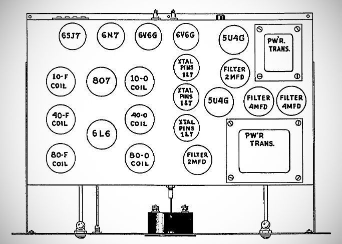
Tube Lineup (8 Tubes):
– Oscillator: 6L6 (using a hot cathode crystal oscillator circuit)
– Final Amplifier: 807
– Speech Amplifier: 6SJ7 (supports crystal or high-impedance dynamic microphones)
– Driver: 6N7 (connected in parallel)
– Modulators: (2) 6V6 tubes (connected in parallel)
– Rectifiers: Two (2) 5U4G (or 5U4) tubes
Dual Power Supply System: To ensure stability, one power supply is dedicated strictly to the 807 final amplifier and the 6V6 modulators, while the other power supply feeds the 6L6 oscillator, 6SJ7 speech amplifier, and 6N7 driver stages.
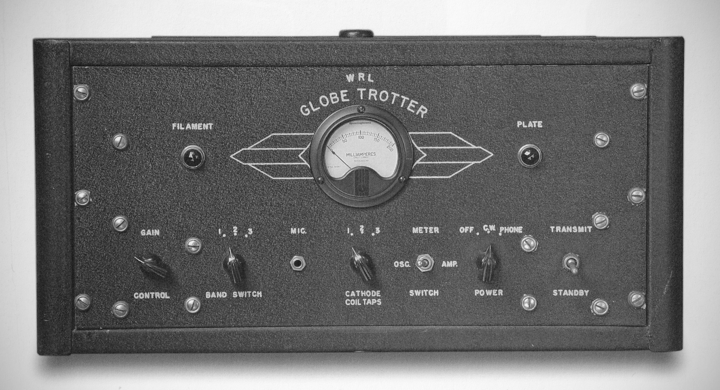
The front panel is designed for rack mounting or enclosure chassis installation and features a symmetric, classic post-war layout:
A large, centrally positioned circular current meter (0–200 mA) with decorative wing/arrow graphics flanking either side. A switch toggles the meter between reading the Oscillator (OSC) or the Final Amplifier (AMP) current.
Band Switch (1, 2, 3): Selects between three sets of pre-plugged oscillator and final plate coils.
Cathode Coil Taps Switch (1, 2, 3): Switches between one of three installed crystals.
Rear Panel
Remote/Antenna Control Terminal Strip: A 4-screw terminal barrier strip labeled `COM-4-8-18` (or similar depending on production revision). The right-hand terminals supply 110V AC when switched to transmit to control an external antenna changeover relay, while the left-hand terminals allow a microphone switch to ground the center taps of the power transformer for remote standby control.
Operating Mechanics & Band Selection
The Globe Trotter uses a plug-in coil system combined with front-panel switching. Up to three sets of oscillator and final coils can be plugged into the top of the chassis at the same time:
– 10-Meter Band: Uses a 40M crystal, 10M oscillator coil, and 10M final coil (Band switch / Cathode switch set to position 3).
– 20-Meter Band: Uses a 40M crystal, 20M oscillator coil, and 20M final coil (Band switch / Cathode switch set to position 3).
– 40-Meter Band: Uses a 40M crystal, 40M oscillator coil, and 40M final coil (Band switch / Cathode switch set to position 2).
– 80-Meter Band: Uses an 80M crystal, 80M oscillator coil, and 80M final coil (Band switch / Cathode switch set to position 1).