Note
Wired only.
CQ, Jul 1962, p. 104.
QST, Aug 1962, p. 149.
QST, Jan 1963, p. 153. (a few details)
QST, Aug 1963, p. 102.
QST, Jan 1964, p. 130.
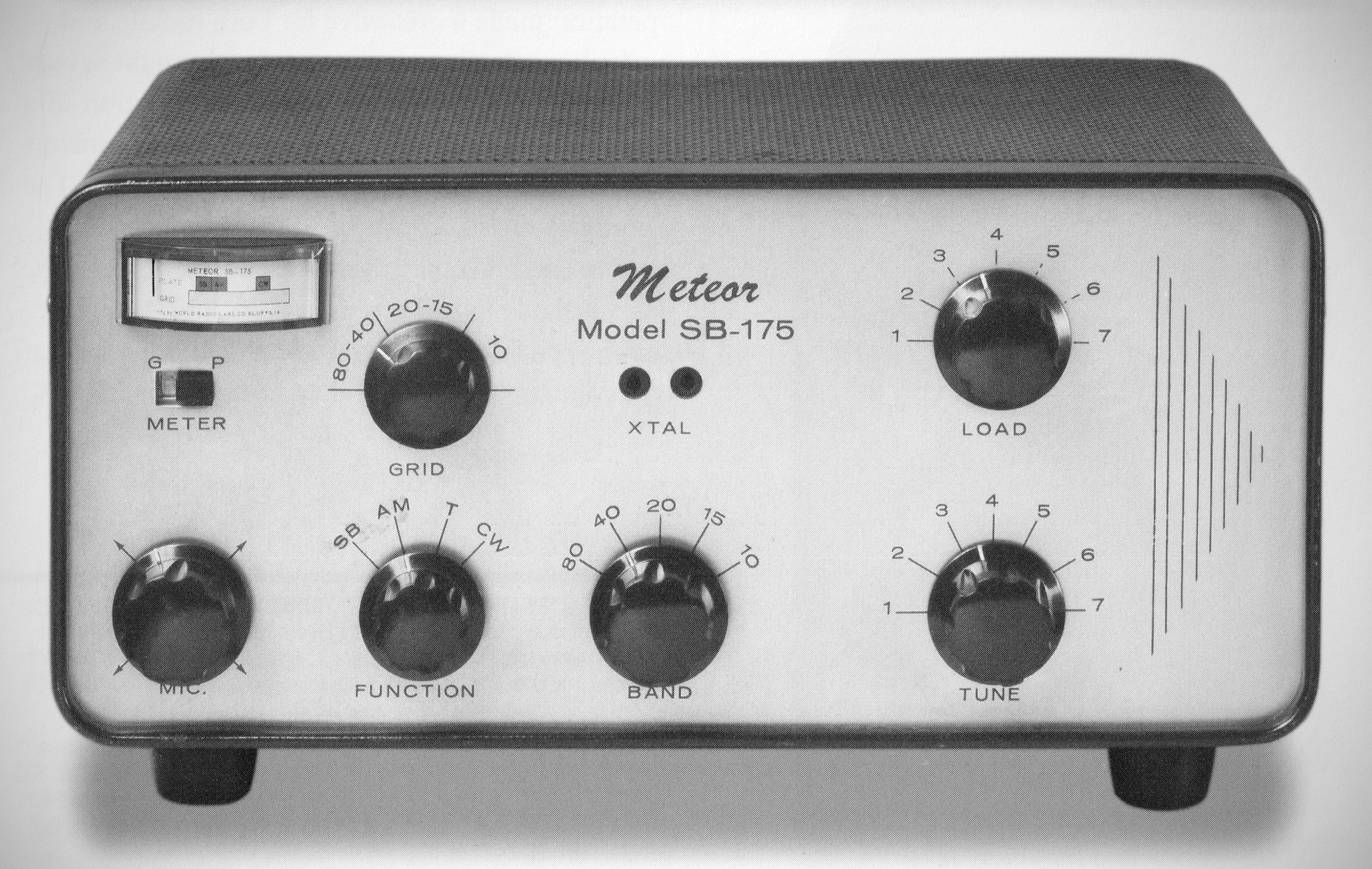
The Meteor transmitted CW, AM, and double sideband, suppressed carrier on 80–10 meters. Power input to the pair of 6DQ6B finals was 175 watts CW, 100 watts AM, and 140 watts DSB. The crystal controlled SB-175 required an external VFO and power supply.
Specifications
– Frequency: Amateur bands 80, 40, 20, 15, and 10 meters, with complete coverage between 3.5 and 9.0 mc for MARS, CAP, or commercial use. – Frequency controlled by front panel crystal or external VFO.
– Modes: CW, AM, DSB.
– Power Input: CW 175 watts; AM 100 watts; DSB 140 PEP watts.
– Power Supply Requirement:
Filament: 6.3 volts @ 4.8 amperes or 12 volts @ 2.4 amperes.
Low B-plus: 300 volts @ 125 milliamperes.
Note: For CW operation, Low B-plus current is reduced to 100 mA.
High B-plus: 600 volts @ 300 milliamperes.
Note: For AM or SB operation, High B-plus current is reduced to 200 mA.
– Audio Input: High-impedance crystal, ceramic, or dynamic microphone. Microphone should have a 3-wire, 0.206" diameter barrel plug (such as Switchcraft S-260, S-290, or 480, or military/surplus PJ-068 or PL-68).
– Carrier Suppression: In DSB operation, the carrier is suppressed approximately 40 decibels below peak output.
Rear socket provides 11 pins for connection to: 6 or 12 volt filament supply, 300 volt and 600 volt B-plus, external VFO, push-to-talk circuit, and 1 unused pin for extra use by the individual. The Mic. Gain Control also operates a filament switch.
Tubes Lineup (6 total):
– 6D10: Compactron audio.
– 6AQ5A: Modulator.
– 6CL6: Oscillator/buffer/multiplier.
– 5763: Multiplier/driver.
– (2) 6DQ6B: Final amplifier.
References
Brief description. Electronics World, Aug 1962, p. 99.
Review. Popular Electronics, Dec 1962, p. 81.