Name/Title
1972- Honeywell-Bull Jr01 (2) **Tags
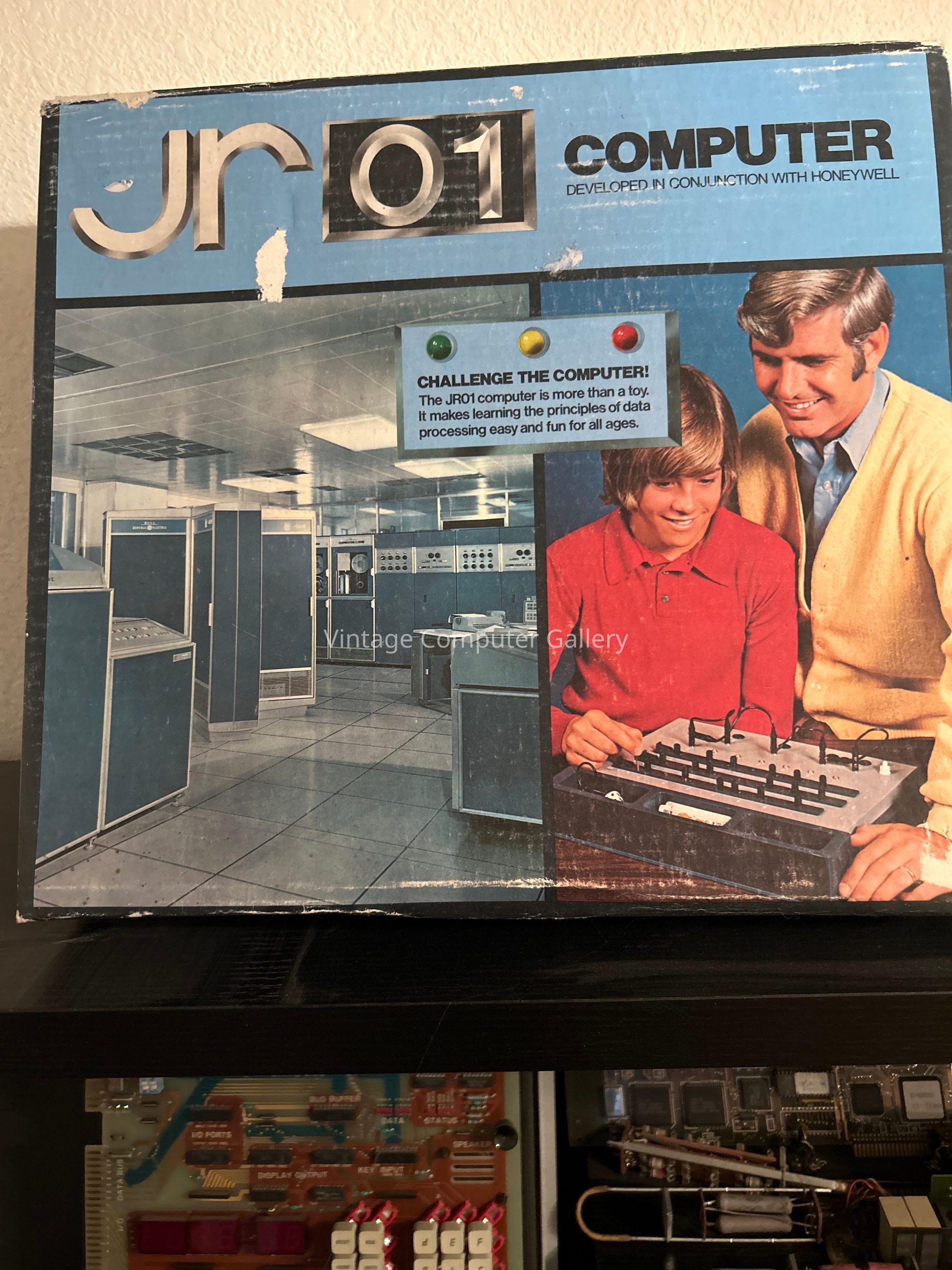
Honeywell-BullDescription
The Jr01 was made in 1972 by Honeywell-Bull.The Jr01 computer consists of three rows, seven columns, four lights, and a button. In each row, each column has two places that a peg can be inserted: a left socket and a right socket. Each row has a long slider switch that contains the peg sockets. By sliding the switch to one side or the other, you can align either the left or right socket with the center of the column. At the bottom of each column, there’s a socket. If the three column sockets that are aligned with the center of the column all have a peg inserted into them, the base socket is “hot” when the button is pressed. At the base of the device, there are four lights, each of which also has a socket. There are several patch cords, each of which has multiple sockets in it so that multiple cords can be combined and plugged into one socket. If one end of the patch cord is connected to the base of a column that is “hot” and the other end is connected to a light, the light turns on when the button is pressed. And that’s the hole, er, whole thing!
A program consists of the placements of pegs and cords into sockets. To run the program, just push the button. Consider this trivial program: if you put a peg in every socket, then pressing the button would activate all seven base sockets. Whichever light was connected by a cord to any socket would light up when the button was pressed.
The Jr01 came with a little booklet, a deck of cards, and a die. The booklet came with a bunch of “programs” that you could enter and little games you could use with it. The games would all ask you three questions, the answers to which would be represented by the positions of the switches, and then the program’s result would be represented by a combination of lights that would light up in response to the answers. The lights were labeled, from left to right, 8, 4, 2, and 1, so adding up the lights would give you an answer ranging from 0 to 15. I learned binary from this toy. I still remember that I had come up with my own binary notation using my diagram of a lit or unlit light. My mathematician uncle told me that that was called binary and that people usually used a “1” to represent “on” and a “0” to represent “off.”